Ublox NINA-B222-04B System Integration Manual Download Page 12


NINA-B2 series - System integration manual 

UBX-18011096 - R05 

Software 


Page 12 of 35 

C1- Public 


RESET_N 


SWITCH_1

 and 

SWITCH_2 

(optional) 

To enable re-programming of the module, UART signals connected to host must not interfere with 
the flashing procedure. UART pins must be put in tri-state by host or have the possibility to 
disconnect completely. Another option is to let host software handle the update procedure (e.g., 
implement the XMODEM protocol or a UART pass-through function). 

2.4


Updating u-connectXpress software with s-center  

The u-connectXpress software, flashed into NINA-B2 module prior to delivery, is used to validate the 
hardware, bootloader, and binary image. The u-connectXpress  software  runs only on validated 
hardware. 

Updates of the u-connectXpress software is available for download fro

www.u-blox.com

. Distributed 

in a single ZIP container, the software includes one binary file and one JSON file that contains the 
software  label, software description, file name, version,  flash  address,  image size,  image  id,  file    
permissions, and signature file for the Connectivity Software application: 


Java Script Object Notation: 

NINA-B22X-CF-<version>.json

. For example: 

NINA-B22X-CF-1.0.json


Connectivity Software: 

NINA-B22X-SW-x.y.z-<build>.bin

. For example: 

NINA-B22X-SW-4.0.0-003.bin


Signature File: 

NINA-B22X-SI-4.0.0-003.bin


To update NINA-B2 u-connectXpress requires s-center software version 4.7 or later. See also the 
s-center user guide [5]. 

Procedure: 

1.


Connect the supplied serial cable on EVK-NINA-B2 to the USB port your computer. For further 
information about setting up EVK-NINA-B2, see also EVK-NINA-B2 user guide [5]. 

2.


Download and the latest version of the s-center and u-connectXpress software from u-blox 

Product Resources

.  See also the EVK-NINA-B2 user guide [5] and s-center user guide [5]. 

3.


Start s-center and choose "USB Serial Port (COMx)" in the drop-down “COM Port” menu. All other 
dialog settings are set to default. 

4.


Select 

Open Port

. A series of AT commands and response are shown in the “Console Window”. 
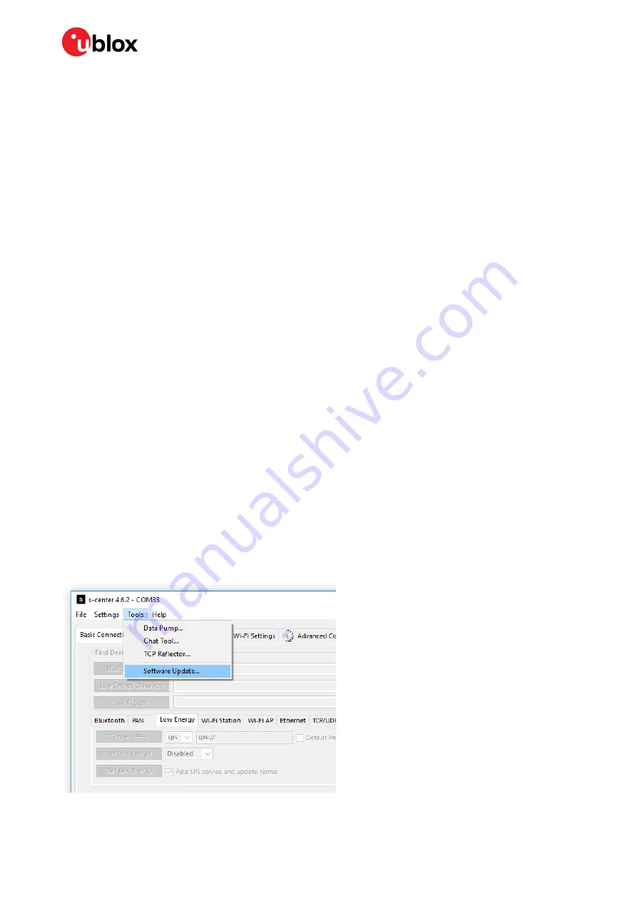
5.


Select 

Tools

 > 

Software Update


Summary of Contents for NINA-B222-04B

Page 1: ...stand alone Bluetooth modules The NINA B2 modules come with pre flashed application software and support dual mode Bluetooth Bluetooth BR EDR and Bluetooth low energy The module has many important sec...

Page 2: ...ised and supplementary data may be published later Mass Production End of Life Production Information Document contains the final product specification This document applies to the following products...

Page 3: ...interface SPI 8 1 8 Antenna interfaces 9 Antenna pin NINA B221 9 Integrated antenna NINA B222 9 1 9 Reserved pins RSVD 9 1 10GND pins 10 2 Software 11 2 1 NINA B2 u connectXpress software 11 2 2 s cen...

Page 4: ...guidelines 25 4 Handling and soldering 26 4 1 ESD handling precautions 26 4 2 Packaging shipping storage and moisture preconditioning 26 4 3 Reflow soldering process 27 Cleaning 28 Other notes 28 5 Ap...

Page 5: ...cons u blox Bluetooth low energy Serial Port Service all configurable from a host using AT commands NINA B222 comes with an internal antenna while NINA B221 has a pin for use with an external antenna...

Page 6: ...maximum antenna gain 3 dBi Table 1 NINA B2 series Bluetooth characteristics 1 3 CPU The NINA B2 series has a dual core system with two Harvard Architecture Xtensa LX6 CPUs with maximum 240 MHz intern...

Page 7: ...ing regulator leads to minimal current saving Linear regulators are not recommended for high voltage step down as they will dissipate a considerable amount of energy DC DC efficiency should be evaluat...

Page 8: ...lso be used for firmware upgrade See also Software The u connectXpress software adds the DSR and DTR pins to the UART interface These pins are not used as they were originally intended but are used in...

Page 9: ...he antenna return loss should be as good as possible across the entire band when the system is operational to provide optimal performance The enclosure shields other components and surrounding environ...

Page 10: ...cription Page 10 of 35 C1 Public 1 10 GND pins Good connection of the module GND pins with solid ground layer of the host application board is required for correct RF performance This significantly re...

Page 11: ...A B2 standalone modules Figure 2 NINA B2 u connectXpress software structure 2 2 s center evaluation software u blox s center client software provides a convenient tool with which to configure u blox s...

Page 12: ...ntains the software label software description file name version flash address image size image id file permissions and signature file for the Connectivity Software application Java Script Object Nota...

Page 13: ...nual 5 and Bootloader protocol specification 5 The bootloader must be running when the software is sent to the module You start the bootloader using either AT commands Pressing the SWITCH_1 and SWITCH...

Page 14: ...ase64 encoded string Enter the 344 character text string defined in the NINA B22X SI x x x xxx txt file name String The name of the firmware Maximum string length is 22 flags String Permissions for us...

Page 15: ...est u connectXpress software from u blox Product Resources 3 Discover the COM port number for the USB Serial Port on your computer MS Windows Start Device Manager Ports See also Setting up the evaluat...

Page 16: ...d the u connectXpress NINA B22X SW 4 0 0 0 003 bin file to NINA B2 5 Once the binary file has been sent NINA B2 displays the greeting text STARTUP Enter the Software version identification AT GMR comm...

Page 17: ...output pins Accurate design is required to guarantee that the voltage level is well defined during module boot Other pins Accurate design is required to guarantee proper functionality 3 2 Supply inte...

Page 18: ...more freedom as an external antenna can be mounted further away from the module According to the FCC regulations the transmission line from the module s antenna pin to the antenna or antenna connector...

Page 19: ...than few centimeters are needed it is recommended to use a coaxial connector and cable to reduce losses o Stack up should allow for thick 50 traces and at least 200 m trace width is recommended to as...

Page 20: ...sical restriction to the PCB design Integrated antenna excites RF currents on its counterpoise typically the PCB ground plane of the device that becomes part of the antenna its dimension defines the m...

Page 21: ...fficiency figure over all the operating frequencies Select antennas that provide appropriate gain figure that is combined antenna directivity and efficiency figure so that the electromagnetic field ra...

Page 22: ...n process should begin at the start of the whole product design process Self made PCBs and antenna assembly are useful in estimating overall efficiency and radiation path of the intended design Use an...

Page 23: ...n interfaces Asynchronous serial interface UART design The layout of the UART bus should be done so that noise injection and cross talk are avoided It is recommended to use the hardware flow control w...

Page 24: ...hing of buses Minimize the routing length longer traces will degrade signal performance Ensure that maximum allowable length for high speed busses is not exceeded Ensure that you track your impedance...

Page 25: ...immunity test to the whole device depends on the device classification as defined by ETSI EN 301 489 1 Applicability of ESD immunity test to the related device ports or the related interconnecting cab...

Page 26: ...o local GND Before mounting an antenna patch connect the device to ground When handling the RF pin do not touch any charged capacitors Be especially careful when handling materials like patch antennas...

Page 27: ...ly recommended The reflow profile used is dependent on the thermal mass of the entire populated PCB the heat transfer efficiency of the oven and the particular type of solder paste that is used The op...

Page 28: ...t Boards with combined through hole technology THT components and surface mount technology SMT devices may require wave soldering to solder the THT components Only a single wave soldering process is a...

Page 29: ...ribed in this document NINA B2 series FCC ID and IC certification number An end product integrating the NINA B2 series module using u blox connectivity software can refer to the u blox FCC ID and IC c...

Page 30: ...ermissive Change depending on the specific antenna and antenna trace design Antennas of the same type and with less or same gain as an already approved antenna can be added under a Class I Permissive...

Page 31: ...rom which a detailed test report for each unit can be generated Figure 10 shows the ATE typically used during u blox production u blox in line production testing includes Digital self tests firmware d...

Page 32: ...circuit if the test result deviates that from that taken against a Golden Device The standard operational module firmware and test software on the host can be used to perform functional tests communic...

Page 33: ...Discharge GND Ground IoT Internet of Things ISM Industrial Scientific and Medical radio LED Light Emitting Diode LTE Long Term Evolution MAC Media Access Control MCU Microcontroller MCS Modulation Co...

Page 34: ...ple on page 2 Provided reference to NINA B2 Getting Started R03 28 Jan 2019 fbro mwej Modified the product status to Initial Production Removed support for external LPO clock section 1 4 1 Updated blo...

Page 35: ...com Regional Office China Beijing Phone 86 10 68 133 545 E mail info_cn u blox com Support support_cn u blox com Regional Office China Chongqing Phone 86 23 6815 1588 E mail info_cn u blox com Suppor...

Reviews: