MAX-M10M - Integration manual
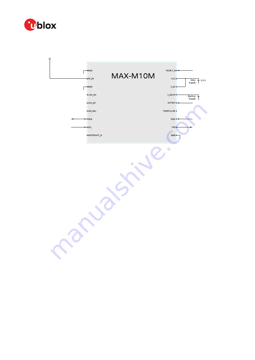
Figure 35: Typical 3.3 V design
UBX-22038241 - R01
Appendix
Page 83 of 90
C1-Public
Page 1: ...manual Abstract This document describes the features and application of the u blox MAX M10M module The MAX M10M module provides an ultra low power standard precision GNSS receiver for high performanc...
Page 2: ...designs included in this document Copying reproduction or modi cation of this document or any part thereof is only permitted with the express written permission of u blox Disclosure to third parties i...
Page 3: ...eceiver reset 32 2 6 Security 33 2 6 1 Con guration locking 33 2 7 Power management 33 2 7 1 Continuous mode 33 2 7 2 Power save mode 34 2 7 3 Backup modes 40 2 8 Time 40 2 8 1 Receiver local time 40...
Page 4: ...3 1 4 Supply design examples 63 3 2 RF interference 64 3 2 1 In band interference 64 3 2 2 Out of band interference 65 3 2 3 Spectrum analyzer 65 3 3 RF front end 66 3 3 1 Internal LNA modes 66 3 3 2...
Page 5: ...1 Standard capacitors 87 C 2 Standard resistors 87 C 3 Inductors 87 C 4 Operational ampli er 87 C 5 Open drain bu ers 87 C 6 Antenna supervisor switch transistors 87 Related documents 88 Revision hist...
Page 6: ...improve the dynamic position accuracy with small antennas or in non line of sight scenarios MAX M10M is cost and power optimized for designs where a SAW lter and an LNA are integrated in the external...
Page 7: ...I System reset active low It has to be low for at least 1 ms to trigger a reset Leave open if not used See RESET_N section for more information 10 GND Connect to GND 11 RF_IN I GNSS signal input The R...
Page 8: ...used leave open Alternative functions 1 17 SCL 3 I I2C clock If not used leave open Alternative functions 1 18 SAFEBOOT_N I Safeboot mode To enter safeboot mode set this pin to low at receiver s start...
Page 9: ...ignal or a UBX CFG RST message with reset mode set to a hardware reset resetMode 0x00 and 0x04 but otherwise will be used as long as the backup battery supply remains CAUTION The con guration interfac...
Page 10: ...2 Internal LNA mode con guration in OTP memory To con gure the internal LNA mode in OTP memory 1 Power up the system 2 Test the communication interface by polling the UBX MON VER message 3 Send the c...
Page 11: ...d individually and the output rate is con gurable The message output rate is related to the frequency of an event For example the output message UBX NAV PVT position velocity and time solution is rela...
Page 12: ...enna supervisor features may require disabling the UART or I2C interface and recon guring the PIOs as antenna supervisor pins Table 4 describes the con guration items Con guration item Description Com...
Page 13: ...st situations Stationary Used in timing applications antenna must be stationary or other stationary applications Velocity restricted to 0 m s Zero dynamics assumed Pedestrian Applications with low acc...
Page 14: ...he atmosphere CFG NAVSPG INFIL_MINSVS CFG NAVSPG INFIL_MAXSVS Minimum and maximum number of satellites to use in the navigation solution There is an absolute maximum limit of 32 satellites that can be...
Page 15: ...the CFG ODO COGMAXSPEED CFG ODO COGMAXPOSACC con guration items are used to con gure a low speed course over ground lter also named heading of motion 2D This lter derives the course over ground from p...
Page 16: ...MAX M10M Integration manual Figure 3 Position output in static hold mode Figure 4 Flowchart of static hold mode UBX 22038241 R01 2 Receiver functionality Page 16 of 90 C1 Public...
Page 17: ...erating conditions low signal strength that is signal attenuation indicates possible degradation due to multi path The receiver trusts such signals less in order to preserve the quality of the positio...
Page 18: ...for a detailed description of the messages The most important SBAS feature for accuracy improvement is the ionosphere correction parameters The measured data from regional Ranging and Integrity Monito...
Page 19: ...lution using correction data to a standard position solution the reference frame of the output position will switch from that of the correction data to that of the standard position solution For an SB...
Page 20: ...over UART and I2C interfaces for communication with a host CPU Each protocol can be enabled on several interfaces at the same time with individual settings for for example baud rate message rates and...
Page 21: ...which should be su cient for most applications However depending on the clock speed of the host and the capacitive load on the I2C lines additional external pull up resistors may be necessary The high...
Page 22: ...c low for write access are clocked onto the bus by the master transmitter The receiver answers with an acknowledge logic low to indicate that it recognizes the address Next the 8 bit address of the re...
Page 23: ...If the master does not read data from the receiver for a certain timeout the receiver assumes that the communication is broken and stops the data stream preventing an over ow of the output bu er This...
Page 24: ...th the CFG I2C ENABLED con guration key if I2C pins are used for antenna supervisor functions 2 3 3 1 RESET_N MAX M10M provides a RESET_N pin to reset the receiver The RESET_N pin is input only with a...
Page 25: ...d The host application can wait on the signal instead of polling the interface The TX ready signal is enabled and assigned to a selected pin with CFG TXREADY con guration items The polarity of the sig...
Page 26: ...d CFG HW_ANT_ con guration items The active antenna status can be determined by polling the UBX MON RF message or checking the NMEA notice messages If an antenna is connected the initial state after p...
Page 27: ...cation Part Description C14 Filtering capacitor L3 DC infeed inductor T1 T2 p channel n channel MOSFET acting as a switch to control the antenna supply U6 Comparator op amp U7 U8 Open drain bu ers to...
Page 28: ...can be supplied by VCC_RF or an external supply Note that the supply voltage must be clean as any noise could directly couple into the RF part of the GNSS receiver which will a ect the overall GNSS p...
Page 29: ...ANTSUPERV AC indicates that antenna control is activated 2 4 1 4 Antenna short detection ANT_SHORT_N Enable the antenna short detection by setting the con guration item CFG HW ANT_CFG_SHORTDET to true...
Page 30: ...nabled to be pulled low if a SHORT is detected Startup message at power up if the con guration is stored GNTXT 01 01 02 ANTSUPERV AC SD PDoS SR 3E GNTXT 01 01 02 ANTSTATUS INIT 3B GNTXT 01 01 02 ANTST...
Page 31: ...rawn from the active antenna OPEN Antenna is not detected That is little or no current is drawn from the active antenna OK Antenna is detected and no short is detected Table 17 Available antenna detec...
Page 32: ...a su cient number of satellites with valid ephemeris the receiver can calculate position and velocity data Other GNSS receiver manufacturers call this startup mode Factory startup Warm start In warm...
Page 33: ...lf There are functions to monitor detect certain security threats and report it to the host system Other functions try to mitigate the threat and allow the receiver to operate normally 2 6 1 Con gurat...
Page 34: ...ion and phases with low or almost no system activity backup sleep In cyclic tracking the receiver does not shut down completely between xes but uses low power tracking instead In PSMOO mode the RAM me...
Page 35: ...g no sky view it will transition to the Inactive for search state after the timeout con gured in MAXACQTIME User con gurable mechanisms MINACQTIME is the minimum time that the receiver will spend in...
Page 36: ...iver to enter the POT state as soon as possible In the POT state the receiver continues to output position xes according to the CFG RATE If the signal becomes weak or is lost during the POT state the...
Page 37: ...l continue with its con gured behavior Enabling EXTINTBACKUP forces the receiver to enter Inactive states for as long as the EXTINT pin is held low until the next wakeup event Any wakeup event can wak...
Page 38: ...POSUPDATEPERIOD ACQPERIOD The update period POSUPDATEPERIOD speci es the time between successive position xes If no position x can be obtained within the acquisition timeout the receiver will retry a...
Page 39: ...AVSPG group Setting harder limits in CFG NAVSPG will typically prolong the time in the Acquisition state When externally controlled it is therefore necessary to ensure su cient time for the receiver a...
Page 40: ...standby mode clears the RAM memory including the receiver con guration To maintain the con guration store it on both RAM and layers The software standby mode can be set for a speci c duration or until...
Page 41: ...RID_TP con guration item allows the user to choose between any of the supported GNSS GPS GLONASS BeiDou etc time bases and UTC Also the CFG NAVSPG UTCSTANDARD con guration item allows the user to sele...
Page 42: ...r its GNSS system time conversion to GPS time requires no work at all but conversion to UTC requires knowledge of the number of leap seconds since GPS time started and other minor correction terms The...
Page 43: ...the time validity can be con rmed by using an additional independent source meaning that the probability of the time to be correct is very high Note that information about time validity con rmation i...
Page 44: ...er appears directly overhead at 0 longitude at midday Occasionally a leap second is announced to bring UTC back into close alignment with the mean solar time Usually this means adding an extra second...
Page 45: ...VER con guration item The following example illustrates how this works Assume that the reference rollover week number set in the rmware at compile time is 2148 which corresponds to a week in calendar...
Page 46: ...eature providing clock pulses with con gurable duration and frequency The time pulse function can be con gured using the CFG TP con guration group The UBX TIM TP message provides time information for...
Page 47: ...applications it is recommended to calibrate the antenna cable delay against a reference timing source To get the best timing accuracy with the antenna a xed and accurate position is needed If relative...
Page 48: ...s set to use another setting in locked mode pulse length ratio Length or duty cycle of the generated pulse speci es either time or ratio for the pulse to be on o pulse length ratio lock Length or duty...
Page 49: ...ormance of the receiver restart Estimate of GNSS time can be maintained by a real time clock or it can be provided to the receiver by the host Estimate of the clock drift of the receiver local oscilla...
Page 50: ...e accurate frequency from satellite transmissions A stable external reference frequency can be used to speed up receiver testing in production test setup The host system may also be able to provide th...
Page 51: ...in one dimension for PL It is not speci ed as a horizontal 2D or 3D value The protection level values UBX NAV PL plPos1 2 3 are con dence intervals around the reported position for example UBX NAV PV...
Page 52: ...ese cases must be checked Only if the PL is set to valid UBX NAV PL plPosValid the PL values UBX NAV PL plPos1 2 3 can be used and are reliable with respect to the target misleading information risk 2...
Page 53: ...k to the receiver when it has been restarted See the description of the UBX MGA DBD messages in the MAX M10M interface description 3 for more information 2 13 3 AssistNow o ine AssistNow O ine is a fe...
Page 54: ...tain a standard HTTP query string in the request URL The query string consists of a set of key value parameters in the following form key value key value key value The following rules apply The order...
Page 55: ...ils can be found in the MAX M10M interface description 3 Where circumstances prevent providing all three of these pieces of data providing some is likely to be better than none at all as this helps to...
Page 56: ...underlying broadcast ephemeris was intended for This makes downloading new ephemeris or aiding data for the rst x unnecessary for subsequent startups of the receiver The AssistNow Autonomous feature...
Page 57: ...nformation only for approximately 30 minutes This is not long enough to extend it in a usable way Orbit information of each GLONASS satellite must be collected at least for four hours to generate data...
Page 58: ...ase of the satellite and Earth and the age of the data errors add up over time AssistNow Autonomous will typically extend a broadcast ephemeris from three up to six days The CFG ANA ORBMAXERR item all...
Page 59: ...the power o state The power down will be delayed until all calculations are done AssistNow Autonomous should be enabled if the system has sporadic access to the AssistNow O ine service In this case th...
Page 60: ...l batched data is lost when the feature is disabled Batched xes are always retrieved starting with the oldest x in the bu er and progressing towards newer ones There is no way to skip certain xes duri...
Page 61: ...format and use satellites only from a limited set of GNSS constellations With the default settings these messages contain measurement data only for a small number of satellites The raw measurement mes...
Page 62: ...is derived from the VCC supply and consequently not available if the VCC supply is removed 3 1 2 V_IO V_IO supplies all the digital IOs clock and the backup domain The current drawn at V_IO depends o...
Page 63: ...21 for designs using the hardware backup mode and Figure 22 for designs without backup supply VIO_SEL is grounded Note that the voltage output at VCC_RF VCC 0 1 V Note that the maximum supply toleranc...
Page 64: ...is less than 128 dBm when reaching the antenna By simply comparing these numbers it is obvious that interference issues must be seriously considered during the design phase 3 2 1 In band interference...
Page 65: ...sily analyzed with this graphical tool The vertical axis compares the amplitude di erence in dB for each frequency A good spectrum shape is characterized by an even noise oor along with the GNSS band...
Page 66: ...lected based on the GNSS performance and RF immunity requirements for the application Alternatively a passive antenna directly connected to the RF input can be used for a lowest cost solution with mod...
Page 67: ...al level modulation and bandwidth of the signal Figure 26 shows a typical out of band immunity level for the MAX M10M RF input The internal LNA is in normal gain mode default The measurement is done a...
Page 68: ...to be considered in lter selection The type and number of lters are selected based on the estimated interference level and the immunity of the receiver RF interference from other parts of the design i...
Page 69: ...ce the RF section and antenna as far away as possible from the other digital circuits on the board Keep at least a 5 mm distance to any RF component and ensure proper grounding For applications using...
Page 70: ...devices cooling fans or thermal conduction via the PCB The GND planes can conduct heat to other elements but they can act as heat dissipators as well Increasing the number of GND vias helps to decreas...
Page 71: ...m pitch and are 0 8 mm wide except the 4 pads at each corner pin 1 9 10 and 18 that are only 0 7 mm Figure 29 and Figure 30 describe the footprint and provide recommendations for the paste mask Note t...
Page 72: ...of the paste mask to form a T shape or equivalent extending beyond the copper mask Recommended stencil thickness is 150 m Figure 30 Recommended paste mask pattern for MAX M10M These are only recommen...
Page 73: ...r example patch antenna 10 pF coax cable 50 80 pF m or soldering iron To prevent electrostatic discharge through the RF input do not touch any exposed antenna area If there is any risk that such expos...
Page 74: ...on reel type as speci ed in the u blox Packaging information reference 4 4 2 2 Tapes Figure 31 shows the feed direction and illustrates the orientation of the components on the tape Figure 31 Orienta...
Page 75: ...nformation reference 4 4 3 Soldering Re ow soldering procedures are described in the IPC JEDEC J STD 020 standard When populating the modules make sure that the pick and place machine is aligned to th...
Page 76: ...erformed excessively ne balls and large balls will be generated in clusters End temperature 150 200 C If the temperature is too low non melting tends to be caused in areas containing large heat capaci...
Page 77: ...odule in particular the quartz oscillators The best approach is to use a no clean soldering paste to eliminate the cleaning step after the soldering Repeated re ow soldering Repeated re ow soldering p...
Page 78: ...Such actions will immediately void the warranty Conformal coating Certain applications employ a conformal coating of the PCB using HumiSeal or other related coating products These materials a ect the...
Page 79: ...red for MAX M8W designs that use V_ANT pin 13 to supply an active antenna SAFEBOOT_N TIMEPULSE The SAFEBOOT_N pin is internally connected to TIMEPULSE pin through a 1 k series resistor Do not drive th...
Page 80: ...con guration MAX M10M GPS Galileo QZSS and SBAS MAX M8Q C W GPS GLONASS QZSS and SBAS Code change optional BeiDou B1C New signal BeiDou satellite IDs up to 63 supported Cannot be used simultaneously w...
Page 81: ...con guration messages Altitude limit The maximum altitude limit increased to 80 000 m Features AssistNow Simultaneous operation of AssistNow Online O ine and Autonomous New AssistNow O ine data downl...
Page 82: ...supply In designs with 3 3 V supply the VIO_SEL pin must be left open as shown in Figure 35 In designs with 1 8 V supply the VIO_SEL pin must be connected to GND as shown in Figure 36 V_BCKP supply is...
Page 83: ...MAX M10M Integration manual Figure 35 Typical 3 3 V design UBX 22038241 R01 Appendix Page 83 of 90 C1 Public...
Page 84: ...e antenna can be supplied with the VCC_RF output from MAX M10M or from an external supply VCC_RF is a ltered output voltage supply which outputs VCC 0 1 V In addition the active antenna supply can be...
Page 85: ...e default no con guration required CFG HW ANT_SUP_SWITCH_PIN 7 default no con guration required CFG HW ANT_CFG_SHORTDET 1 true CFG HW ANT_CFG_SHORTDET_POL 0 false CFG HW ANT_SUP_SHORT_PIN 5 CFG HW ANT...
Page 86: ..._SWITCH_PIN 7 default no con guration required CFG HW ANT_CFG_SHORTDET 1 true CFG HW ANT_CFG_SHORTDET_POL 0 false CFG HW ANT_SUP_SHORT_PIN 3 CFG HW ANT_CFG_OPENDET 1 true CFG HW ANT_CFG_OPENDET_POL 1...
Page 87: ...le 37 Standard resistors C 3 Inductors Table 38 presents the recommended inductor values for MAX M10M Name Use Type Value Recommended component L3 RF Bias T inductor 27 nH 5 Murata LQG15H LQW15A serie...
Page 88: ...22001426 3 u blox M10 SPG 5 10 Interface description UBX 21035062 4 u blox Packaging information reference UBX 14001652 For regular updates to u blox documentation and to receive product change noti...
Page 89: ...MAX M10M Integration manual Revision history Revision Date Name Status comments R01 12 Jan 2023 imar jesk mban msul rmak Initial release UBX 22038241 R01 Revision history Page 89 of 90 C1 Public...
Page 90: ...Integration manual Contact u blox AG Address Z rcherstrasse 68 8800 Thalwil Switzerland For further support and contact information visit us at www u blox com support UBX 22038241 R01 Page 90 of 90 C...