


EVK-MAYA-W2 - User guide
UBX-22011269 - R04
Board description
Page 18 of 20
C1 – Public
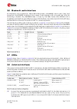
The antenna interface of EVK-MAYA-W276 can be changed to SMA connector J11 by removing 0
Ω
resistor R29 and populating R28 instead, as shown in
Figure 12: Hardware modification to use SMA connector J11 on EVK-MAYA-W276
3.9
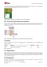
RF control and coexistence interfaces
shows the module RF control signals and the WCI-2 coexistence interface accessible on pin
header J12. The external PTA coexistence interface of MAYA-W2 is shared with the SPI pins on J13
as described in
Figure 13: Host interface configuration, RF control, and WCI-2 coexistence interfaces (J12)
3.10
LEDs
describes the function and designation of the available LEDs on the EVK-MAYA-W2
evaluation board.
Function
Description
Designator
Color
Supply
Board 3.3 V and 1.8 V power supply status indication
D2
Green
UART
UART RX/TX activity indication
D3
Orange
Table 11: LED function
3.11
Reset button
Press the SW1 button on the EVB to reset the MAYA-W2 module. When pressed, SW1 asserts the
PDn
pin of the MAYA-W2 module to enter power down mode, while keeping the supply rails enabled.
The module is automatically reset when it exits the power down mode, which means that the firmware
must be downloaded again.
3.12
Schematics
Complete schematics for the MAYA-W2 evaluation board are available on request. For further
information,
your local u-blox support team.
R28
R29


