


C099-F9P - User guide
UBX-18063024 - R16
Using C099-F9P
Page 16 of 43
C1-Public
Figure 12: The supplied GNSS multi-band antenna
4.3
User interfaces
C099-F9P has a number of fixed connection options besides the wireless modes. There is also an
additional Arduino R3 / Uno interface for external host connection.
The USB connector on the board provides connection via an on-board hub providing:
•
An FTDI USB bridge to ZED-F9P UART1 and ODIN-W2 UART COM ports.
•
Dedicated connection to the ZED-F9P USB port.
FTDI USB bridge
When the USB cable from the user’s PC is connected, a driver load
s and sets up two virtual serial ports,
as shown below in Figure 13. Additionally, a further serial VCP is created to provide a direct connection
with the ZED-F9P USB port.
☞
Ensure that the PC is connected to the internet to load the drivers from Windows Update.
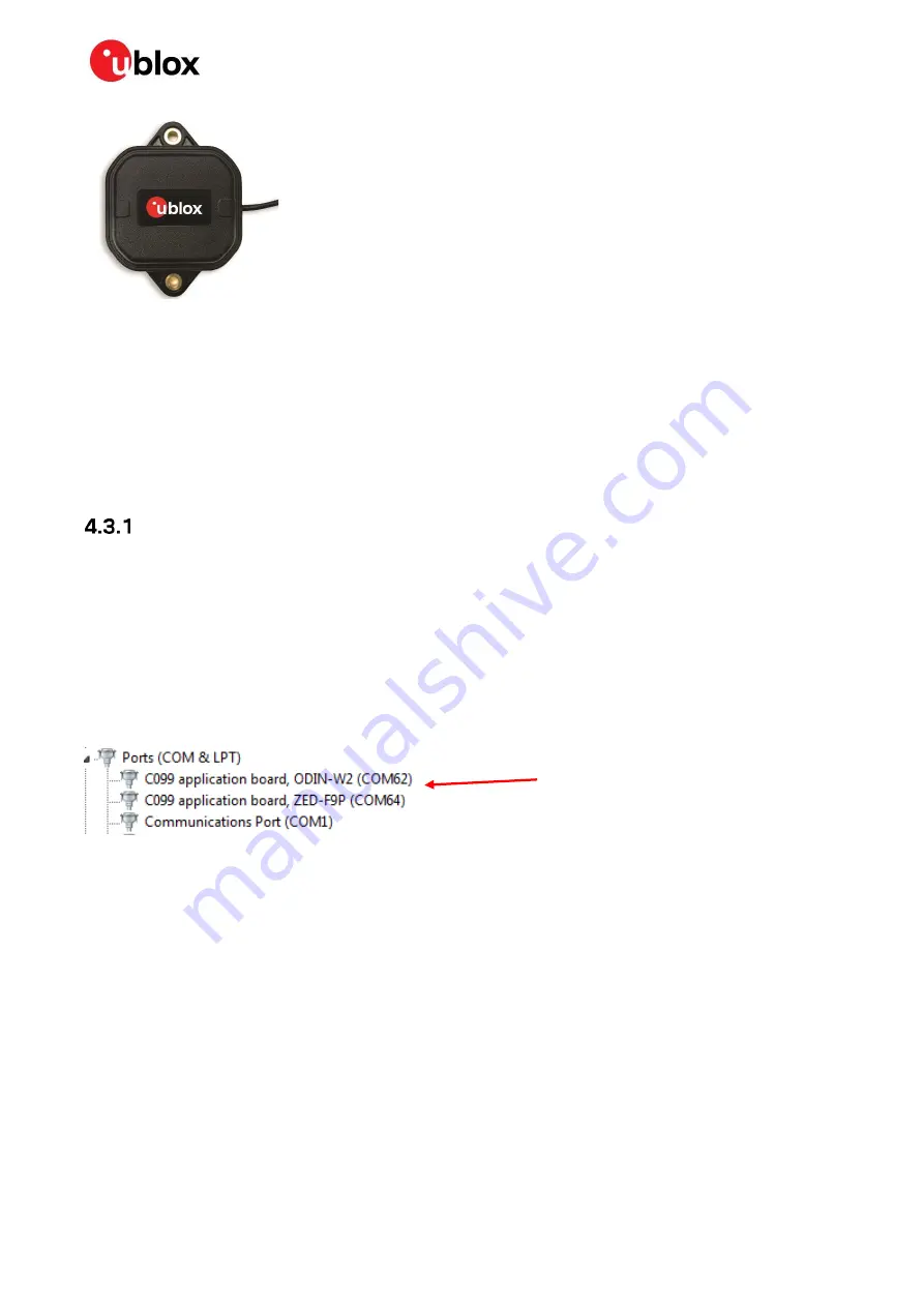
The first of these is connected to the ZED-F9P serial port and should be selected with u-center. The
second serial device is for the ODIN-W2 module when using s-center. In Figure 13, the ODIN-W2
connection is the first port (COM 62) and the ZED-F9P connection is the second port (COM 64). Port
numbering can be different between individual PCs, but the same arrangement applies.
Figure 13: Windows Device Manager COM port view
In addition, a third VCP is created corresponding to the ZED-F9P USB port. Windows 10 users see a
new VCP device in the Device Manager window when it loads a built-in driver. With older Windows
installations, a driver is loaded via Windows Update. In this case the device is identified as a u-blox
GNSS device in the Device Manager window.
Open u-center (V18.12 or later), select the ZED-F9P serial port, and set the baud rate to 460800 to
match the ZED-F9P default UART setting. Once connected, u-center shows typical received signal
levels from multiple GNSS bands, see Figure 14 below.
ZED-F9P and ODIN-W2
COM ports installed


