Ubiquiti UVC-G3-DOME Quick Start Manual Download Page 20

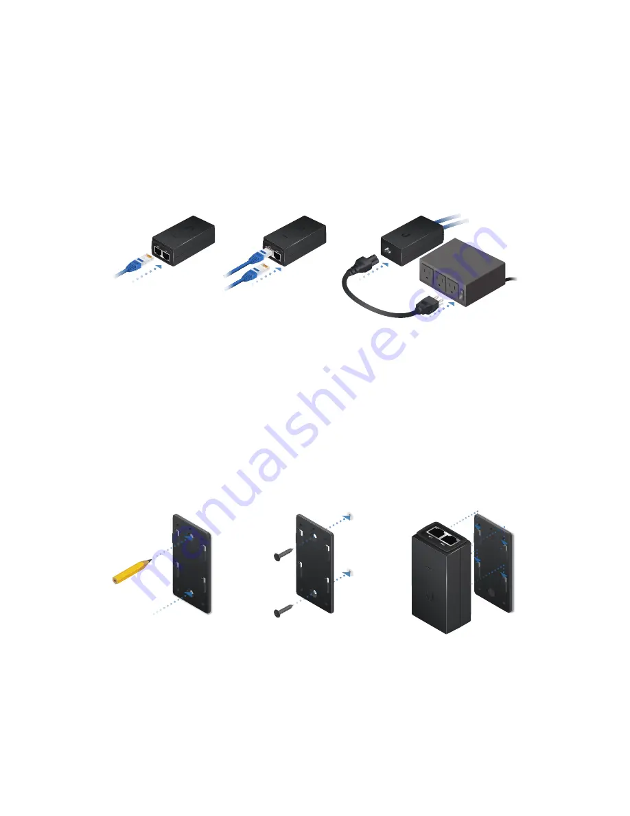
Connecting to a PoE Adapter

1.  Connect the Ethernet cable from the UniFi Video Camera 

to the POE port of the PoE Adapter.

2.  Connect an Ethernet cable from your LAN to the LAN port  

of the PoE Adapter. 

3.  Connect the Power Cord to the adapter, and then plug the 

Power Cord into a power outlet.

Mounting the PoE Adapter (Optional)

1.  Remove the PoE Mounting Bracket from the adapter, place 

the bracket at the desired location, and mark the two holes. 

2.  Pre-drill the holes if necessary, and secure the bracket 

using two fasteners (not included).

3.  Align the slots on the adapter with the tabs of the PoE 

Mounting Bracket, and then slide the adapter down.

Summary of Contents for UVC-G3-DOME

Page 1: ...DOME Wide Angle 1080p Dome IP Camera with Infrared Model UVC G3 DOME...

Page 2: ...E Screw Anchors M3x20 Qty 4 PoE Adapter 24V 0 5A with Mount Bracket Power Cord Quick Start Guide Only the single pack of the UVC G3 DOME includes a PoE adapter and a power cord TERMS OF USE All Ethern...

Page 3: ...UVC G3 DOME in an open environment Mounting location should be at least 60 cm 2 ft from the edge of the eave or ceiling Cable feed must be pointed downwards when wall mounted Shielded Category 5 or ab...

Page 4: ...the rubber Cable Gland is installed for added protection Security Slot Mounting Bracket Security Slot If you need to remove the UniFi Video Camera from the Mounting Bracket insert a paper clip in the...

Page 5: ...NVR Upon adoption the LED will light steady blue for 10 minutes and then turn off Ethernet The Ethernet port is a 10 100 Ethernet port used to connect the power and should be connected to the LAN and...

Page 6: ...Position the Mounting Bracket at the desired location on the wall with the Arrow pointing up 2 Mark the four mounting holes and use a 6 mm drill bit to drill the holes Arrow 3 If your Ethernet cable...

Page 7: ...ors into the 6 mm holes Secure the Mounting Bracket to the wall by inserting the Screws into the anchors 5 Remove the Cable Gland from the UniFi Video Camera Note For indoor installations use of the C...

Page 8: ...1 04 6 Feed the Ethernet cable through the cable opening on the Cable Gland Note The feed hole will stretch to accommodate the RJ45 connector and then seal around the cable 7 Connect the Ethernet cabl...

Page 9: ...8 Replace the Cable Gland 9 If the Ethernet cable is fed through the wall skip to step 10 If the Ethernet cable runs along the mounting surface route the cable inside the cable channel...

Page 10: ...10 Align the four tabs on the Mounting Bracket with the four slots on the bottom of the camera Lock Tab 11 Rotate the camera clockwise until the tabs lock into place and the Lock Tab engages...

Page 11: ...nd rotate the bracket to the desired direction of the camera view Mark the four mounting screw holes and an 18 mm hole for the Ethernet cable feed Direction of Camera View 18 mm Hole for Ethernet Cabl...

Page 12: ...4 Insert the Flat Head Screws through the Mounting Bracket ceiling tile and Ceiling Backing Plate Fasten the screws using the Keps Nuts Then feed the Ethernet cable through the tile and bracket...

Page 13: ...eo Camera Note For indoor installations use of the Cable Gland is optional 6 Feed the Ethernet cable through the cable opening on the Cable Gland Note The feed hole will stretch to accommodate the RJ4...

Page 14: ...7 Connect the Ethernet cable to the Ethernet port 8 Replace the Cable Gland...

Page 15: ...r tabs on the Mounting Bracket with the four slots on the bottom of the camera Lock Tab 10 Rotate the camera clockwise until the tabs lock into place and the Lock Tab engages 11 Set the ceiling tile b...

Page 16: ...tight seal between the Lens Cover and the camera body Rotate the Lens Cover with your hand to break the seal Do not use any tools 2 Pivot the Lens Cover away from the camera body and remove it Protec...

Page 17: ...3 Rotate the camera body toward the desired view 4 Tilt and rotate the camera lens assembly to set the desired view angle...

Page 18: ...e Lens Cover by aligning the two small rib tabs on the cover with the two slots on the camera body 6 Ensure the Lens Cover is evenly seated and then push down and rotate the cover 10 clockwise to lock...

Page 19: ...witch Ubiquiti Networks PoE Adapter 24V 0 5A The single pack of the UVC G3 DOME includes one PoE adapter For multi pack units PoE adapters or a UniFi Switch may be purchased separately Connecting to a...

Page 20: ...Cord to the adapter and then plug the Power Cord into a power outlet Mounting the PoE Adapter Optional 1 Remove the PoE Mounting Bracket from the adapter place the bracket at the desired location and...

Page 21: ...wnloads ubnt com unifivideo The UniFi Video auto management feature should automatically detect your new camera s To manage the camera perform the following steps 1 Click the Unmanaged tab 2 Click the...

Page 22: ...list Note You may need to update the firmware from the Firmware tab to complete the camera installation UniFi Video App The UniFi Video mobile app is available for free in the App Store for iOS devic...

Page 23: ...aximum Frame Rate 30 FPS Image Settings Brightness Contrast Sharpness Saturation Noise Reduction 50 60 Hz Microphone Yes Processor Ambarella S2L63 816 MHz ARM Cortex A9 Memory Information 512 MB DDR3L...

Page 24: ...vice should be provided only by a qualified service technician 3 This equipment is provided with a detachable power cord which has an integral safety ground wire intended for connection to a grounded...

Page 25: ...V has been subjected to misuse abuse negligence abnormal physical electromagnetic or electrical stress including lightning strikes or accident V has been damaged or impaired as a result of using third...

Page 26: ...FACILITIES UBIQUITI NETWORKS ITS AFFILIATES AND ITS AND THEIR THIRD PARTY PROVIDERS ARE NOT RESPONSIBLE FOR ANY INTERRUPTIONS DELAYS CANCELLATIONS DELIVERY FAILURES DATA LOSS CONTENT CORRUPTION PACKET...

Page 27: ...the equipment This device complies with Part 15 of the FCC Rules Operation is subject to the following two conditions 1 This device may not cause harmful interference and 2 This device must accept any...

Page 28: ...ment please contact your local authorities waste disposal service or the shop where you purchased the product Deutsch Die Europ ische Richtlinie 2002 96 EC verlangt dass technische Ausr stung die dire...

Page 29: ...insi que tout autre mat riel lectrique ou lectronique par les moyens de collecte indiqu s par le gouvernement et les pouvoirs publics des collectivit s territoriales L limination et le recyclage en bo...

Page 30: ...aisten vaatimusten ja muiden sit koskevien direktiivin 1999 5 EY Fran ais French Par la pr sente UBIQUITI NETWORKS d clare que l appareil UBIQUITI NETWORKS est conforme aux exigences essentielles et a...

Page 31: ...i verensst mmelse med de v sentliga egenskapskrav och vriga relevanta best mmelser som framg r av direktiv 1999 5 EG Espa ol Spanish Por medio de la presente UBIQUITI NETWORKS declara que este disposi...

Page 32: ...nd UniFi are trademarks or registered trademarks of Ubiquiti Networks Inc in the United States and in other countries App Store is a service mark of Apple Inc Google Android Google Play and other mark...

Reviews: