background image

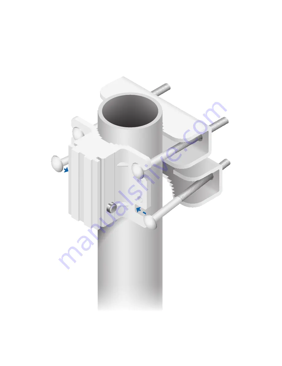
3.  Uniformly hand-tighten each Flange Nut. Ensure the Pole 

Clamp is evenly clamped around the pole and tighten each 
Flange Nut to approximately 25 N-m (18 lb-ft).

4.  Attach the other Pole Clamp to the pole by sliding the 

Carriage Bolts around the pole and into the bottom two 
slots of the Mounting Bracket. 

5.  Uniformly hand-tighten each Flange Nut. Ensure the Pole 

Clamp is evenly clamped around the pole and tighten each 
Flange Nut to approximately 25 N-m (18 lb-ft).

Summary of Contents for UAP-AC

Page 1: ...Enterprise WiFi System Model UAP AC Outdoor ...

Page 2: ...ware for mounting the unit on a wall or a pole Installation Requirements 13 mm wrench Shielded Category 5 or above cabling should be used for all outdoor wired Ethernet connections and should be grounded through the AC ground of the PoE We recommend that you protect your networks from brutal outdoor environments and devastating ESD attacks with industrial grade shielded Ethernet cable from Ubiquit...

Page 3: ...M8 Qty 4 Enterprise WiFi System Model UAP AC Outdoor PoE GigE Adapter 48V 0 5A Gigabit Power Cord Quick Start Guide System Requirements Microsoft Windows Vista Windows 7 Windows 8 or Mac OS X Java Runtime Environment 1 6 or above Web Browser Mozilla Firefox Google Chrome or Microsoft Internet Explorer 8 or above ...

Page 4: ...unning the UniFi Controller software located either onsite and connected to the same Layer 2 network or off site in a cloud or NOC or Router Off Site Cloud NOC On Site Management Station UAP PRO UAP AC Outdoor UAP AC UAP Outdoor Sample Network Diagram All UniFi APs support off site management controllers For setup details refer to the User Guide on the website documentation ubnt com unifi ...

Page 5: ... upgrade is taking place Quickly Flashing Blue This is used to locate an AP When you click Locate in the UniFi Controller software the AP will flash It will also display the location of the AP on the map Steady Blue Indicates the device has been successfully integrated into a network and is working properly Steady Blue with occasional flashing Indicates the device is in an isolated state all WLANs...

Page 6: ... AP Restart Press and release the Reset button quickly Restore to Factory Default Settings Press and hold the Reset button for more then five seconds Main The Main port is a Gigabit Ethernet port used to connect the power and should be connected to the LAN and DHCP server Power can be provided by any of the following PoE GigE adapter included 48V 802 3at compliant switch Ubiquiti Networks TOUGHSwi...

Page 7: ...hardware Pole Mount 1 Insert two Carriage Bolts into each Pole Clamp and install the Flange Nuts as far down the bolts as necessary to accommodate the pole Note The mounting assembly can accommodate a Ø 1 5 3 0 pole 2 Attach one of the Pole Clamps to the pole by sliding the Carriage Bolts around the pole and into the top two slots of the Mounting Bracket ...

Page 8: ...approximately 25 N m 18 lb ft 4 Attach the other Pole Clamp to the pole by sliding the Carriage Bolts around the pole and into the bottom two slots of the Mounting Bracket 5 Uniformly hand tighten each Flange Nut Ensure the Pole Clamp is evenly clamped around the pole and tighten each Flange Nut to approximately 25 N m 18 lb ft ...

Page 9: ...ket a Position the UniFi AP with the Mounting Bracket aligned between the mounting tabs on the back of the UniFi AP b Slide the UniFi AP downward into the grooves of the Mounting Bracket until the snap pins engage and lock the UniFi AP in place ...

Page 10: ...The Mounting Bracket must attach directly to a stud or other structurally stable surface 1 Locate the stud 2 Position the Mounting Bracket on the stud ensuring at least two holes are centered on the stud 3 Mark all four holes on the wall 4 Drill pilot holes as necessary 5 Secure the Mounting Bracket to the wall with four fasteners ...

Page 11: ...ket a Position the UniFi AP with the Mounting Bracket aligned between the mounting tabs on the back of the UniFi AP b Slide the UniFi AP downward into the grooves of the Mounting Bracket until the snap pins engage and lock the UniFi AP in place ...

Page 12: ...be powered by the included PoE GigE Adapter or a compatible PoE switch 1 Lift the locking tab of the Port Cover and slide the cover down to remove it MAIN RESET SECONDARY 2 Connect an Ethernet cable to the Main port 3 Replace the Port Cover ...

Page 13: ...her end of the Ethernet cable to the Ethernet port labeled POE on the PoE GigE Adapter 2 Connect an Ethernet cable from your LAN to the Ethernet port labeled LAN on the PoE GigE Adapter 3 Connect the power cord the PoE GigE Adapter and to a power outlet ...

Page 14: ...i Controller software at downloads ubnt com unifi and follow the on screen instructions After you have installed the software and run the UniFi Installation Wizard a login screen will appear for the UniFi Controller management interface Enter the Admin Name and Password that you created and click Login You can manage your wireless network and view network statistics using the UniFi Controller mana...

Page 15: ...DC Power Supply 48V 0 5A PoE Gigabit Adapter Included Max Power Consumption 22 W BSSID Up to Four per Radio Power Save Supported Wireless Security WEP WPA PSK WPA TKIP WPA2 AES 802 11i Certifications CE FCC IC Mounting Wall Pole Kits Included Operating Temperature 10 to 55 C Operating Humidity 5 80 Condensing Antennas 2 4 GHz 3 Integrated Supports 3x3 MIMO with Spatial Diversity 5 GHz 3 Integrated...

Page 16: ...provided only by a qualified service technician 3 This equipment is provided with a detachable power cord which has an integral safety ground wire intended for connection to a grounded safety outlet a Do not substitute the power cord with one that is not the provided approved type Never use an adapter plug to connect to a 2 wire outlet as this will defeat the continuity of the grounding wire b The...

Page 17: ...IV has been subjected to misuse abuse negligence abnormal physical electromagnetic or electrical stress including lightning strikes or accident V has been damaged or impaired as a result of using third party firmware VI has no original Ubiquiti MAC label or is missing any other original Ubiquiti label s or VII has not been received by Ubiquiti within 30 days of issuance of the RMA In addition the ...

Page 18: ... FACILITIES UBIQUITI NETWORKS ITS AFFILIATES AND ITS AND THEIR THIRD PARTY PROVIDERS ARE NOT RESPONSIBLE FOR ANY INTERRUPTIONS DELAYS CANCELLATIONS DELIVERY FAILURES DATA LOSS CONTENT CORRUPTION PACKET LOSS OR OTHER DAMAGE RESULTING FROM ANY OF THE FOREGOING In addition UBIQUITI NETWORKS does not warrant that the operation of the Products will be error free or that operation will be uninterrupted ...

Page 19: ... for compliance could void the user s authority to operate the equipment This device complies with Part 15 of the FCC Rules Operation is subject to the following two conditions 1 This device may not cause harmful interference and 2 This device must accept any interference received including interference that may cause undesired operation NOTE This equipment has been tested and found to comply with...

Page 20: ...unication réussie Cet appareil est conforme à la norme RSS Industrie Canada exempts de licence norme s Son fonctionnement est soumis aux deux conditions suivantes 1 Cet appareil ne peut pas provoquer d interférences et 2 Cet appareil doit accepter toute interférence y compris les interférences qui peuvent causer un mauvais fonctionnement du dispositif RF Exposure Warning The antennas used for this...

Page 21: ...ce or the shop where you purchased the product Deutsch Die Europäische Richtlinie 2002 96 EC verlangt dass technische Ausrüstung die direkt am Gerät und oder an der Verpackung mit diesem Symbol versehen ist nicht zusammen mit unsortiertem Gemeindeabfall entsorgt werden darf Das Symbol weist darauf hin dass das Produkt von regulärem Haushaltmüll getrennt entsorgt werden sollte Es liegt in Ihrer Ver...

Page 22: ...nsi que tout autre matériel électrique ou électronique par les moyens de collecte indiqués par le gouvernement et les pouvoirs publics des collectivités territoriales L élimination et le recyclage en bonne et due forme ont pour but de lutter contre l impact néfaste potentiel de ce type de produits sur l environnement et la santé publique Pour plus d informations sur le mode d élimination de votre ...

Page 23: ...õhinõuetele ja nimetatud direktiivist tulenevatele teistele asjakohastele sätetele Suomi Finnish UBIQUITI NETWORKS vakuuttaa täten että UBIQUITI NETWORKS device tyyppinen laite on direktiivin 1999 5 EY oleellisten vaatimusten ja sitä koskevien direktiivin muiden ehtojen mukainen Français French Par la présente UBIQUITI NETWORKS déclare que l appareil UBIQUITI NETWORKS device est conforme aux exige...

Page 24: ... t mto vyhlasuje e UBIQUITI NETWORKS device sp a základné po iadavky a v etky príslu né ustanovenia Smernice 1999 5 ES Svenska Swedish Härmed intygar UBIQUITI NETWORKS att denna UBIQUITI NETWORKS device står I överensstämmelse med de väsentliga egenskapskrav och övriga relevanta bestämmelser som framgår av direktiv 1999 5 EG Español Spanish Por medio de la presente UBIQUITI NETWORKS declara que el...

Reviews: