background image

Connect the power using one of the following options: 

•  Using the included Gigabit PoE Adapter: Go to 

Connecting to the PoE Adapter.

•  Using a separate PoE switch: Connect the Ethernet 

cable from the device’s Main Ethernet port to a  
PoE‑enabled Ethernet port on the switch.

WARNING:

 The switch port must comply with the 

power specifications listed in the Specifications 
section of this Quick Start Guide.

Connecting to the PoE Adapter

1.  Connect the Ethernet cable from the device’s Ethernet port 

to the POE port of the Gigabit PoE adapter.

2.  Connect an Ethernet cable from your LAN to the adapter’s 

LAN port. 

3.  Connect the Power Cord to the adapter’s power port. 

Connect the other end of the Power Cord to a power outlet.

Mounting the PoE Adapter (Optional)

1.  Remove the PoE Mounting Bracket from the adapter, place 

the bracket at the desired location, and mark the two holes. 

2.  Pre‑drill the holes if necessary, and secure the bracket 

using two fasteners (not included).

3.  Align the adapter’s slots with the tabs of the PoE Mounting 

Bracket, and then slide the adapter down.

Summary of Contents for PowerBeam AC PBE-5AC-620

Page 1: ...High Performance Integrated InnerFeed airMAX ac Bridge Model PBE 5AC 620 ...

Page 2: ...Flange Nuts Qty 2 M8 Flange Nuts Qty 4 High Performance Integrated InnerFeed airMAX ac Bridge Model PBE 5AC 620 M8x150 Carriage Bolts Qty 4 Pole Clamps Qty 2 Gigabit PoE 24V 0 5A with Mounting Bracket Power Cord Quick Start Guide TERMS OF USE Ubiquiti radio devices must be professionally installed Shielded Ethernet cable and earth grounding must be used as conditions of product warranty TOUGHCable...

Page 3: ... for more than 10 seconds while the PowerBeam is powered on Alternatively the PowerBeam may be reset remotely via a Reset button located on the bottom of the Gigabit PoE Adapter Release Button After you assemble the PowerBeam check the Release button it should be fully engaged in the Release Button Slot of the Rear Housing This ensures that the Antenna Feed is locked into place If you need to remo...

Page 4: ...is made and flash when there is activity Signal In airOS you can modify the threshold value for the wireless signal strength LEDs on the Wireless tab under Signal LED Thresholds Each LED will light when the wireless signal strength is equal to or greater than the LED s threshold value The default threshold values for these LEDs are shown below 65 dBm 73 dBm 80 dBm 94 dBm ...

Page 5: ... dBi Antenna Feed only Installation Requirements Phillips screwdriver 13 mm wrench 16 mm wrench Shielded Category 5 or above cabling should be used for all wired Ethernet connections and should be grounded through the AC ground of the PoE We recommend that you protect your networks from harmful outdoor environments and destructive ESD events with industrial grade shielded Ethernet cable from Ubiqu...

Page 6: ...Door and detach it from the Rear Housing Keep the Cable Door detached b Press the Release Button and slide the Rear Housing off of the Antenna Feed 2 Line up the Alignment Pins of the Rear Housing with the alignment holes of the Dish Reflector Insert the pins and push until they lock into place ...

Page 7: ...o place with a click b Lightly pull the Antenna Feed to ensure that it is locked into place and the Release button is fully engaged Release Button Bottom View 4 Connect the Ethernet cable a Connect an Ethernet cable to the Ethernet Port of the Antenna Feed b Re attach the Cable Door to the Rear Housing ...

Page 8: ...ket Note Ensure that each Lock Washer is always installed between the Hex Head Bolt and Flat Washer Flat Washer Lock Washer Hex Head Bolt 8 mm 6 Attach the horizontal slot of the Support Arm to the Upper Pole Bracket using a Hex Head Bolt Lock Washer and Flat Washer Note Ensure that the degree settings are the same on both arms of the Upper Pole Bracket Degree markings facing outward ...

Page 9: ...7 Attach the Brace to the pole brackets using the four Screws ...

Page 10: ...tach one Pole Clamp to each pole bracket a Insert two M8x150 Carriage Bolts into each pole bracket b Slide the hole of a Pole Clamp over one bolt of each pole bracket c Place one M8 Flange Nut on each bolt ...

Page 11: ...where the PowerBeam will be attached Note The pole bracket assembly can accommodate a Ø 38 101 mm pole a Place one Stabilizer Bracket on each side of the pole b Insert the two M10x100 Bolts into the Stabilizer Brackets c Secure each bolt with one M10 Flange Nut 50 N m ...

Page 12: ...ket assembly to the pole a Slide the slot of each Pole Clamp over the corresponding M8x150 Carriage Bolt b Tighten the M8 Flange Nuts of the bolts to secure the pole bracket assembly to the pole Proper slot orientation 25 N m ...

Page 13: ... and align the two lower Hex Head Bolts with the slots on the Lower Pole Bracket Seat the bolts in the slots 12 Attach each arm of the Upper Pole Bracket to the Mounting Bracket using a Hex Head Bolt Lock Washer and Flat Washer ...

Page 14: ...ent IMPORTANT If you cannot spin the washers freely by hand then loosen the Hex Head Bolts until you can 14 To adjust the tilt angle turn the screw head of the elevation rod until the desired tilt is reached 15 Lock the alignment by tightening all Hex Head Bolts to 25 N m 640 00136 07 640 00136 07 ...

Page 15: ...1 Connect the Ethernet cable from the device s Ethernet port to the POE port of the Gigabit PoE adapter 2 Connect an Ethernet cable from your LAN to the adapter s LAN port 3 Connect the Power Cord to the adapter s power port Connect the other end of the Power Cord to a power outlet Mounting the PoE Adapter Optional 1 Remove the PoE Mounting Bracket from the adapter place the bracket at the desired...

Page 16: ...rname and Password fields Select your Country and Language You must agree to the Terms of Use to use the product Click Login 620 Note The Country setting for U S product versions is restricted to a choice of Canada Puerto Rico or the U S to ensure compliance with FCC IC regulations The airOS Configuration Interface will appear allowing you to customize your settings as needed For details refer to ...

Page 17: ...ler s responsibility to make sure the device is operated within local country regulatory requirements Since Ubiquiti Networks equipment can be paired with a variety of antennas and cables the Antenna and Output Power fields are provided to the professional installer to assist in meeting regulatory requirements ...

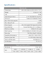
Page 18: ...4V 0 5A Gigabit PoE Supply Included Power Method Passive PoE Pairs 4 5 7 8 Return Wind Survivability 200 km h 125 mph Wind Loading 872 N 200 km h 196 lbf 125 mph Mounting Pole Mounting Kit Included Operating Temperature 40 to 70 C 40 to 158 F Operating Humidity 5 to 95 Noncondensing Shock and Vibrations ETSI300 019 1 4 Certifications CE FCC IC Operating Frequency MHz Worldwide 5150 5875 USA U NII ...

Page 19: ... provided only by a qualified service technician 3 This equipment is provided with a detachable power cord which has an integral safety ground wire intended for connection to a grounded safety outlet a Do not substitute the power cord with one that is not the provided approved type Never use an adapter plug to connect to a 2 wire outlet as this will defeat the continuity of the grounding wire b Th...

Page 20: ...n addition made thereto except by Ubiquiti Networks or Ubiquiti Networks authorized representatives or as approved by Ubiquiti Networks in writing II has been painted rebranded or physically modified in any way III has been damaged due to errors or defects in cabling IV has been subjected to misuse abuse negligence abnormal physical electromagnetic or electrical stress including lightning strikes ...

Page 21: ...OVIDERS CONTROL BUYER S EQUIPMENT OR THE TRANSFER OF DATA OVER COMMUNICATIONS FACILITIES INCLUDING THE INTERNET AND THAT THE PRODUCTS AND SERVICES MAY BE SUBJECT TO LIMITATIONS INTERRUPTIONS DELAYS CANCELLATIONS AND OTHER PROBLEMS INHERENT IN THE USE OF COMMUNICATIONS FACILITIES UBIQUITI NETWORKS ITS AFFILIATES AND ITS AND THEIR THIRD PARTY PROVIDERS ARE NOT RESPONSIBLE FOR ANY INTERRUPTIONS DELAY...

Page 22: ...two conditions 1 This device may not cause harmful interference and 2 This device must accept any interference received including interference that may cause undesired operation This equipment has been tested and found to comply with the limits for a Class A digital device pursuant to Part 15 of the FCC Rules These limits are designed to provide reasonable protection against harmful interference w...

Page 23: ...vice Antenna Information Dish antenna Gain 29 dBi CAN ICES 3 A NMB 3 A Le présent appareil est conforme aux CNR d ISDE Canada applicables aux appareils radio exempts de licence L exploitation est autorisée aux deux conditions suivantes 1 l appareil ne doit pas produire de brouillage 2 l appareil doit accepter tout brouillage radioélectrique subi même si le brouillage est susceptible d en compromet...

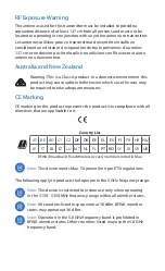
Page 24: ...e user may be required to take adequate measures CE Marking CE marking on this product represents the product is in compliance with all directives that are applicable to it Country List AT BE BG CY CZ DE DK EE EL ES FI FR HR HU IE IT LV LT LU MT NL PL PT RO SE SI SK UK BFWA Broadband Fixed Wireless Access members noted in blue Note This device meets Max TX power limit per ETSI regulations The foll...

Page 25: ...ce or the shop where you purchased the product Deutsch Die Europäische Richtlinie 2012 19 EU verlangt dass technische Ausrüstung die direkt am Gerät und oder an der Verpackung mit diesem Symbol versehen ist nicht zusammen mit unsortiertem Gemeindeabfall entsorgt werden darf Das Symbol weist darauf hin dass das Produkt von regulärem Haushaltmüll getrennt entsorgt werden sollte Es liegt in Ihrer Ver...

Page 26: ...que tout autre matériel électrique ou électronique par les moyens de collecte indiqués par le gouvernement et les pouvoirs publics des collectivités territoriales L élimination et le recyclage en bonne et due forme ont pour but de lutter contre l impact néfaste potentiel de ce type de produits sur l environnement et la santé publique Pour plus d informations sur le mode d élimination de votre anci...

Page 27: ...stenmukaisuusvakuutuksen täysimittainen teksti on saatavilla seuraavassa internetosoitteessa www ubnt com compliance Français French Le soussigné UBIQUITI NETWORKS déclare que l équipement radioélectrique du type PBE 5AC 620 est conforme à la directive 2014 53 UE Le texte complet de la déclaration UE de conformité est disponible à l adresse internet suivante www ubnt com compliance Deutsch German ...

Page 28: ... UBIQUITI NETWORKS týmto vyhlasuje že rádiové zariadenie typu PBE 5AC 620 je v súlade so smernicou 2014 53 EÚ Úplné EÚ vyhlásenie o zhode je k dispozícii na tejto internetovej adrese www ubnt com compliance Slovenščina Slovenian UBIQUITI NETWORKS potrjuje da je tip radijske opreme PBE 5AC 620 skladen z Direktivo 2014 53 EU Celotno besedilo izjave EU o skladnosti je na voljo na naslednjem spletnem ...

Reviews: