background image

Installation Requirements

The NanoBeam can be mounted on a pole or to a wall. A Metal 
Strap
 (included) is used for pole-mounting. For wall-mounting, 
a suitable fastener such as a screw or bolt (not included) is 
required.
•  7 mm (¼ in) socket wrench or screwdriver (for 

pole-mounting)

•  Wall fastener (for wall-mounting)
•  Shielded Category 5 (or above) cabling should be used for 

all wired Ethernet connections and should be grounded 
through the AC ground of the PoE.
We recommend that you protect your networks from the 
most brutal environments and devastating ESD attacks with 
industrial-grade shielded Ethernet cable, TOUGHCable from 
Ubiquiti Networks.

For more details, visit www.ubnt.com/toughcable

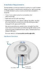
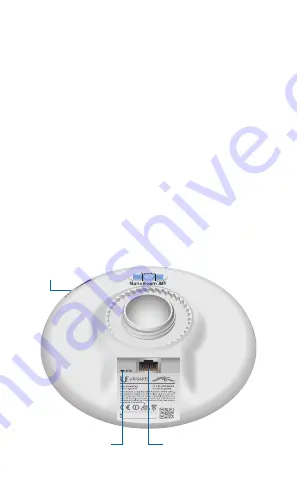
Hardware Overview

LEDs

Reset Button

Ethernet Port 

(10/100 Mbps)

Summary of Contents for NBE-M5-16

Page 1: ...High Performance 16 dBi airMAX CPE Model NBE M5 16...

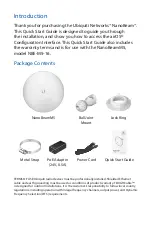
Page 2: ...5 Ball Joint Mount Lock Ring High Performance 16 dBi airMAX CPE Model NBE M5 16 Metal Strap PoE Adapter 24V 0 5A Power Cord Quick Start Guide TERMS OF USE Ubiquiti radio devices must be professionally...

Page 3: ...all fastener for wall mounting Shielded Category 5 or above cabling should be used for all wired Ethernet connections and should be grounded through the AC ground of the PoE We recommend that you prot...

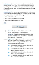
Page 4: ...EdgeRouter PoE LEDs Power The Power LED will light blue when the device is connected to a power source Ethernet The Ethernet LED will light steady blue when an active Ethernet connection is made and f...

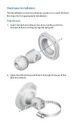
Page 5: ...e or to a wall Perform the steps for the appropriate installation Pole Mount 1 Insert the Ball Joint Mount into the Lock Ring with the threads of the Lock Ring facing the ball joint 2 Open the Metal S...

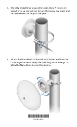
Page 6: ...se a 7 mm in socket drive or screwdriver to turn the screw clockwise and securely fasten the strap to the pole 4 Attach the NanoBeam to the Ball Joint Mount and turn the Lock Ring to secure it Keep th...

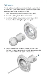
Page 7: ...Mark the desired location of the mounting point 2 If needed drill a pilot hole for the fastener 3 Insert the Ball Joint Mount into the Lock Ring with the threads of the Lock Ring facing the ball joint...

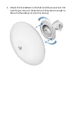
Page 8: ...5 Attach the NanoBeam to the Ball Joint Mount and turn the Lock Ring to secure it Keep the Lock Ring loose enough to allow the NanoBeam to pivot for aiming...

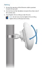
Page 9: ...et cable is pointed towards the ground 2 Aim the front of the NanoBeam towards the other end of the wireless link 3 Hand tighten the Lock Ring to lock the aim Note Do not use a tool to tighten the Loc...

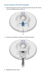
Page 10: ...Connecting to the PoE Adapter 1 Remove the port cover by pressing down the center of the cover and sliding the cover out 2 Connect an Ethernet cable to the Ethernet port 3 Replace the port cover...

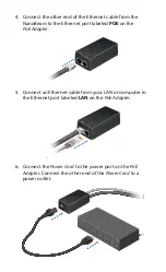
Page 11: ...Ethernet port labeled POE on the PoE Adapter 5 Connect an Ethernet cable from your LAN or computer to the Ethernet port labeled LAN on the PoE Adapter 6 Connect the Power Cord to the power port on the...

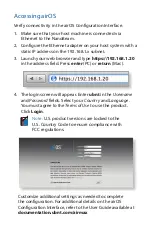
Page 12: ...dress field Press enter PC or return Mac 4 The login screen will appear Enter ubnt in the Username and Password fields Select your Country and Language You must agree to the Terms of Use to use the pr...

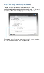
Page 13: ...nally installed and it is the professional installer s responsibility to make sure the device is operated within local country regulatory requirements The Output Power field is provided to the profess...

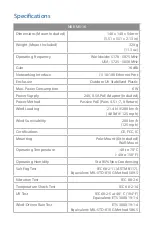
Page 14: ...Power Method Passive PoE Pairs 4 5 7 8 Return Wind Loading 21 4 N 200 km h 4 8 lbf 125 mph Wind Survivability 200 km h 125 mph Certifications CE FCC IC Mounting Pole Mount Kit Included Wall Mount Oper...

Page 15: ...rovided only by a qualified service technician 3 This equipment is provided with a detachable power cord which has an integral safety ground wire intended for connection to a grounded safety outlet a...

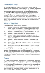
Page 16: ...V has been subjected to misuse abuse negligence abnormal physical electromagnetic or electrical stress including lightning strikes or accident V has been damaged or impaired as a result of using third...

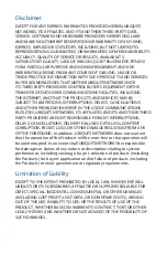
Page 17: ...FACILITIES UBIQUITI NETWORKS ITS AFFILIATES AND ITS AND THEIR THIRD PARTY PROVIDERS ARE NOT RESPONSIBLE FOR ANY INTERRUPTIONS DELAYS CANCELLATIONS DELIVERY FAILURES DATA LOSS CONTENT CORRUPTION PACKET...

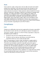
Page 18: ...pressly approved by the party responsible for compliance could void the user s authority to operate the equipment This device complies with Part 15 of the FCC Rules Operation is subject to the followi...

Page 19: ...ommunication r ussie Cet appareil est conforme la norme RSS Industrie Canada exempts de licence norme s Son fonctionnement est soumis aux deux conditions suivantes 1 Cet appareil ne peut pas provoquer...

Page 20: ...ice or the shop where you purchased the product Deutsch Die Europ ische Richtlinie 2002 96 EC verlangt dass technische Ausr stung die direkt am Ger t und oder an der Verpackung mit diesem Symbol verse...

Page 21: ...insi que tout autre mat riel lectrique ou lectronique par les moyens de collecte indiqu s par le gouvernement et les pouvoirs publics des collectivit s territoriales L limination et le recyclage en bo...

Page 22: ...ORKS seadme UBIQUITI NETWORKS device vastavust direktiivi 1999 5 E p hin uetele ja nimetatud direktiivist tulenevatele teistele asjakohastele s tetele Suomi Finnish UBIQUITI NETWORKS vakuuttaa t ten e...

Page 23: ...NETWORKS device sp a z kladn po iadavky a v etky pr slu n ustanovenia Smernice 1999 5 ES Svenska Swedish H rmed intygar UBIQUITI NETWORKS att denna UBIQUITI NETWORKS device st r I verensst mmelse med...

Page 24: ...U logo the Ubiquiti beam logo airMAX airOS EdgeRouter NanoBeam TOUGHCable and TOUGHSwitch are trademarks or registered trademarks of Ubiquiti Networks Inc in the United States and in other countries A...

Reviews: