background image


UAV-1004233-001, AV-30-E Pilot’s Guide 

28 

Revision A


7.2 Brightness Menu 

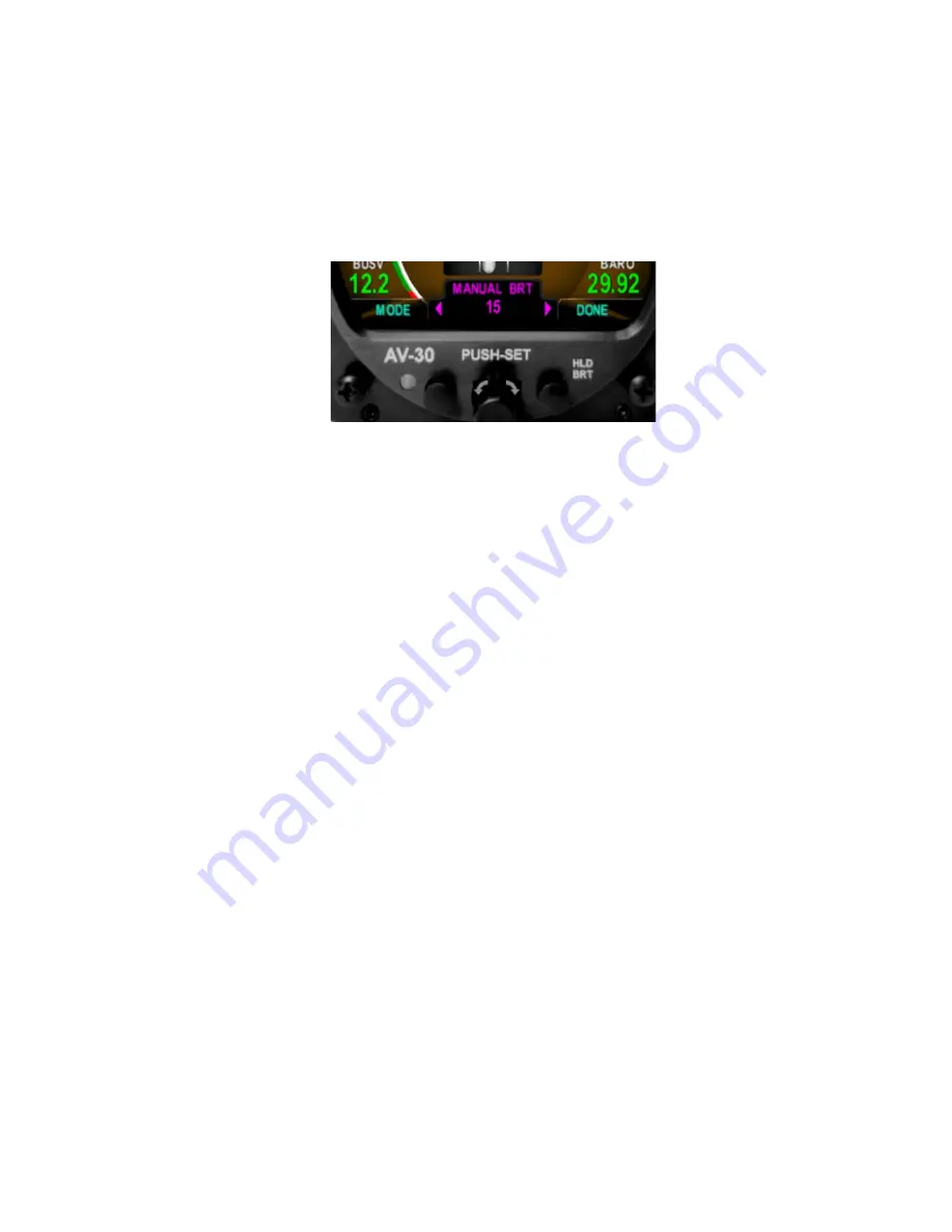
The Brightness Menu is activated by pressing and holding the lower 

right button 


Figure 23 - Brightness Menu 

The left button toggles between AUTO BRT (Automatic brightness 

mode), and MANUAL BRT (Manual brightness mode).   
When in manual brightness mode, the display brightness can be 

adjusted from 1 to 100 utilizing the rotary knob.  When in automatic 

brightness mode, the display brightness is set automatically based on 

the bezel-mounted photocell. 
Pressing the DONE button will exit the Brightness Menu. 


Summary of Contents for AV-30-E

Page 1: ...UAV 1004233 001 AV 30 E Pilot s Guide 1 Revision A AV 30 E Pilot s Guide ...

Page 2: ...nload a single copy of this guide onto an electronic storage medium to be viewed for personal use provided that the complete text of this copyright notice is retained Unauthorized commercial distribution of this manual or any revision hereto is strictly prohibited uAvionix and Ping are registered trademarks of uAvionix Corporation and may not be used without express permission of uAvionix AV 30 AV...

Page 3: ...UAV 1004233 001 AV 30 E Pilot s Guide 3 Revision A 1 Revision History Revision Date Comments A 6 2 2020 Initial release ...

Page 4: ...ification Number ECCN 7A994 These items are controlled by the U S Government and authorized for export only to the country of ultimate destination for use by the ultimate consignee or end user s herein identified They may not be resold transferred or otherwise disposed of to any other country or to any person other than the authorized ultimate consignee or end user s either in their original form ...

Page 5: ...T Probe Optional 13 5 6 Audio Output Optional 14 6 User Interface 14 6 1 Startup and Common Controls 14 6 2 AI Mode Display Components 15 6 2 1 AI Mode Basic Components 15 6 2 2 AI Mode Attitude Slip 17 6 2 3 AI Mode Airspeed Indicator 17 6 2 4 AI Mode Flight Direction Indicator 18 6 2 5 AI Mode Baro Corrected Altitude Indicator 19 6 2 6 AI Mode AoA Indication 21 6 2 7 AI Mode Vertical Trend Indic...

Page 6: ...4 AI DG Displayable Parameters 33 8 User Interface and Font Style Options 35 9 Alerts and Alert Limits 37 10 Internal Battery Operation 38 10 1 General 38 10 2 Battery Transition Logic 38 10 2 1 Power On Self Test Pre Flight 38 10 2 2 Power Loss Airspeed Above 40 kts In Flight 39 10 2 3 Power Loss Airspeed Below 40 kts On Ground 39 10 3 Battery Charge Status 39 11 AoA Operation and Configuration 3...

Page 7: ...UAV 1004233 001 AV 30 E Pilot s Guide 7 Revision A 12 1 Pilot Accessible Setup Menu 47 12 2 Non Pilot Accessible Install Menu 47 13 Operating Limits System Specifications 47 13 1 Operating Limits 50 ...

Page 8: ...can be customized by the pilot to show a variety of textual and graphical data overlay fields Three pages may be customized by the pilot while a fourth page presents a fully decluttered view of only attitude and slip When configured as a Directional Gyro DG direction of flight information is presented The flight direction can be configured to be presented as non slaved heading or inertially stabil...

Page 9: ... applications A wide variety of supplemental functions including audio alerting derived angle of attack presentation G load display and more are provided An internal rechargeable LiPo battery allows for operation for a nominal 2 hours in the event of aircraft power loss and 30 minutes minimum under all temperature conditions ...

Page 10: ...dicated Airspeed Altitude V Speeds Angle Of Attack Vertical Trend Vertical Speed Set Altitude Heading Bus Voltage G Load Outside Air Temp True Airspeed Density Altitude GPS Navigator Waypoint Data GPS Navigator Nav Data GPS Navigator Route Line Heading Bug Audio and Visual Alerting Functions AoA Alerting G Limit Alerting Excessive Roll Alerting Misc Functions Internal Battery Operation Auto Manual...

Page 11: ... the AI and DG installation configurations Note that some interfaces are optional and may not be available in a given installation Aircraft Power Pitot System Static System ELECTRICAL INTERFACES Digital Optional OAT Probe Analog Optional Audio Out Analog AIRCRAFT SYSTEMS Optional GPS Navigator AV 30 E PNEUMATIC CONNECTORS Figure 2 AV 30 E Aircraft Systems Interfaces AI Mode ...

Page 12: ...nal OAT probe is equipped 5 2 Power Input Required Power input is required in both AI and DG configurations and each unit has a dedicated circuit breaker The power input is internally diode OR ed with the unit s internal battery via a processor controlled switch This architecture allows the unit to continue operation if external power fluctuates or is completely lost When external power is supplie...

Page 13: ... This is a text binary protocol output by the GPS navigator that contains situational awareness information such as ground speed track distance to destination cross track etc and is typically utilized by remote mapping display products to provide additional pilot awareness This output does not provide IFR compliant lateral or vertical guidance therefore all deviation related data presented is for ...

Page 14: ...ircraft s non switched audio input on the audio panel Audio alerting thresholds and enable disable of the alerts are configured by the pilot in the Setup Menu Audio alerting is only supported when configured as an AI 5 7 tailBeaconX Control Optional The AV 30 E has the option of being the transponder control interface for an installed tailBeaconX allowing the user to change the Mode and Squawk inp...

Page 15: ...play Figure 5 Common User Interface Components Press and hold the center knob to switch between AI and DG mode when Function Lock is disabled See section 13 Install Menu Activation 6 2 AI Mode Display Components The following section describes the user interface operations when operating as an AI 6 2 1 AI Mode Basic Components The following figure shows the basic AI with all customizable data over...

Page 16: ...ical located in the non utilized areas of the display area Customizable InnerGraphical Fields 3Total Customizable DataOverlay Fields 6Total Figure 7 Data Overlay Examples There are three independently customizable pages which are selected round robin fashion by sequentially pressing the Page Selection button shown as page 1 of 3 in the figures above A fourth fully decluttered page allows all suppl...

Page 17: ... On initial startup the red ALIGN flag will flash indicating that the attitude is still stabilizing The aircraft should be held as motionless as possible during the aligning process When the ALIGN flag is displayed the presented attitude may be incorrect 6 2 3 AI Mode Airspeed Indicator Indicated airspeed can be configured for display on the left side of the screen The configured units KTS or MPH ...

Page 18: ...cated airspeed numerals will turn yellow when operating in the yellow speed arc red when operating in a red speed arc but are otherwise white Vfe Vs1 Vs0 Vno Vne ColorCoded Presentation Figure 10 V Speed Limits On initial startup the airspeed field will be dashed while sensor stabilization occurs Airspeed display units and v Speed limits are configured during installation and are not pilot accessi...

Page 19: ...ed arrow will show the shortest turn direction to the corresponding bug Figure 11 AI Mode Direction Indication Bearing To Off Screen 6 2 5 AI Mode Baro Corrected Altitude Indicator Baro corrected altitude can be configured for display on the right side of the screen and shows the baro altitude in feet When this field is configured for altitude display the lower right field will be locked to the ba...

Page 20: ... while sensor stabilization occurs On unit power down the current field elevation and barometric pressure are stored in internal non volatile memory On the next power up this field elevation is utilized to reverse compute and estimated baro setting potentially reducing the required adjustment amount required by the pilot During this reverse computation process the baro value will be shown in light...

Page 21: ...ds to a current AoA matching the configured lower limit point The first red bar corresponds to a current AoA matching the configured upper limit AoA limit points are pilot selectable and are set in the pilot accessible Setup Menu Figure 13 AI Mode AoA Indication AoA is determined by the difference between the aircrafts pitch angle and the path through the air See Section 11 AoA Operation and Confi...

Page 22: ...cal Trend Indication 6 2 8 AI Mode G Load Indicator The current G Load can be configured for display on the inner right or left area of the screen and consists of a ball marker on a background scale The upper and lower limits of the scale correspond to the upper and lower G limits set in the pilot accessible Setup Menu Figure 16 AI Mode G Load Indication The center most tic mark represents 1 0 G V...

Page 23: ...isplay screen can be configured to show various textual parameters Figure 17 AI Mode Text Fields If a given parameter is invalid or currently unavailable it will be presented as a dashed field See Section 7 4 AI DG Displayable Parameters for which parameters can be configured for display in these fields ...

Page 24: ... textual fields are available for customization HeadingBug Display Mode Textual Overlays PageSelection Textual Overlays Figure 18 Basic DG Mode User Interface 6 3 2 DG Mode GPS HSI Mode The display type can also be configured to show GPS nav data when connected to an external GPS navigator and presented in the traditional HSI format BearingTo HeadingBug Display Mode GPSTrack Course To FixedDeviati...

Page 25: ...ptoArc innm Nav Mode VFROnly RouteLeg Display Scale Adjust Figure 20 GPS ARC Mode The entire programmed flight plan is not displayed only the current nav leg and current waypoint The display scale is adjusted by rotating the rotary knob and represents the display distance from the own ship icon to the outer compass ring The following scales may be selected for display Selectable Display Scales 1 2...

Page 26: ...o vertical deviations are shown and lateral deviations are not scaled for approach IFR operations Air data temperature related parameters TAS DALT OAT are only available if the DG has been connected to and OAT probe otherwise they will not be selectable for display The currently displayed GPS track may optionally be gyroscopically stabilized allow smoother operation when in turns This option is co...

Page 27: ...rent configuration of the display The following indicates how baro is adjusted when altitude has been configured for display Figure 22 Push Set Example Baro Rotating the knob when this is displayed will change the baro setting If however the display is configured NOT to show altitude the baro setting will not be presented as an option to adjust Push Set Value When Presented Baro Setting When altit...

Page 28: ...e left button toggles between AUTO BRT Automatic brightness mode and MANUAL BRT Manual brightness mode When in manual brightness mode the display brightness can be adjusted from 1 to 100 utilizing the rotary knob When in automatic brightness mode the display brightness is set automatically based on the bezel mounted photocell Pressing the DONE button will exit the Brightness Menu ...

Page 29: ...e Outer Textual Fields Inner Graphical Fields Outer Textual Fields Figure 24 Customizable Field Locations AI Mode There are three independent pages that can be configured as desired The fourth page is not configurable In general is it suggested that the display be customized prior to flight and that each page be setup for the different basic modes of flight operations Departure Enroute Terminal pr...

Page 30: ...the cursor can be moved to each customizable area by rotating the rotary knob Figure 25 UI Customization Menu Entry The currently selected field will be indicated by a darkened block with a cyan bracket Rotating the knob left and right will change the currently selected field To edit the overlay value presented in the currently highlighted field push the rotary knob Figure 26 UI Customization Fiel...

Page 31: ...n will accept the current value and the edit mode will remain active Pressing the DONE shown in the lower left button will accept the current value and exit the UI customization mode Figure 27 Display Edit Value Note that not all data values can be presented in each editable field area For example airspeed will only be displayed on the left main area and altitude will only be displayed on the righ...

Page 32: ...ilized to enter and exit the customization mode Editing the upper most field will change the overall direction indication between basic ROSE presentation GPS HSI presentation and the GPS arc presentation The individual textual fields may also be selected and customized All three pages of the DG can be customized in a similar manner Figure 28 DG Mode UI Customization ...

Page 33: ...must be installed for this parameter to be selectable The GPS field indicates that a connection to an external GPS navigator is required for the parameter to be selectable Data Type Presentation AI Mode DG Mode OAT GPS Blank Overlay Field N A Attitude Graphical Non Slaved Heading Graphical Bus Voltage Textual G Load Value Textual G Load Indicator Graphical Indicated Airspeed Textual Baro Corrected...

Page 34: ...4 Revision A Direction Rose Graphical Direction Arc Graphical Direction HSI Graphical GPS Navigator Data Textual GPS HSI Indicator Graphical GPS Navigator Route Graphical Heading Bug Graphical Figure 29 Data Overlay Types vs Operational Mode ...

Page 35: ...e Mode Press in the center knob Press the right button to cycle through each Mode selection STBY ON ALT Press the left button DONE to finish To Ident Press the left button Quick Squawk 1200 Press in the center knob Press in the center knob to select a squawk digit Press the right button to quick squawk 1200 Press the left button DONE to finish A Configured Callsign B Current Squawk Code C Mode Sel...

Page 36: ...tic styles and two different fonts are selectable by the pilot The three UI styles are LEGACY EFIS and VINTAGE The two font selections are ARIAL and LCD These settings only effect the displayed colors and font style all functional operations are identical regardless of the style settings Figure 30 UI Style Options ...

Page 37: ...ght alerts are exclusive of each other and therefore have the same priority level Type Priority Percent Aural Visual Roll Left 7 100 Roll Left Amber ROLL LEFT Roll Right 7 100 Roll Right Amber ROLL RIGHT AoA 6 80 One Tone Amber ANGLE AoA 5 90 Two Tones Amber ANGLE AoA 4 100 Check Angle Red ANGLE G Load 3 80 One Tone Amber G LOAD G Load 2 90 Two Tones Amber G LOAD G Load 1 100 G Limit Red G LOAD Ta...

Page 38: ...ure range 10 2 Battery Transition Logic The battery is tested enabled and disabled based on airspeed and aircraft bus voltage as follows 10 2 1 Power On Self Test Pre Flight On powerup the battery charge status will show TEST in amber During this process an internal load is being applied to the battery to determine general capacity capability If the battery fails this self test the charge status f...

Page 39: ... on ground and the bus voltage drops below 7 VDC the unit will initiate a shut down sequence This is the normal on ground shutdown method Pilot may abort the shutdown with any knob or button push If bus voltage returns the shutdown sequence will automatically be aborted and the unit will return to normal operating mode 10 3 Battery Charge Status The battery charge state is shown in percentage An i...

Page 40: ...t this directly corresponds to the angle at which the wing is intercepting the body of air surrounding the aircraft with correlates to the current AoA Pitch is determined by the precision internal AHRS and flight path angle is determined by air data based airspeed versus vertical speed measurements Angle Of Attack Pitch Angle Flight Path Level Ref Pitch Angle AHRS Measured Pitch Flight Path Angle ...

Page 41: ...o the corresponding AoA display The upper near stall configuration limit is set when the aircraft is in the base to final configuration with flaps and gear set to their normal positions for this maneuver This provides the best protection when the aircraft is low and slow and the pilot may inadvertently stall based on over corrections The upper limit is configured to coincide with the aircrafts exi...

Page 42: ... set the upper limit the following procedure is recommended At a safe altitude suitable for stalls configure the aircraft for the normal base to final turn typically gear and partial flaps extended Slowly reduce speed and maintain a constant altitude monitoring the display AoA as the aircrafts angle of attack increases If the aircrafts stall warning occurs prior to the indicator reaching the first...

Page 43: ...te operation with one or two lower green bars illuminated Configure the aircraft for normal en route operation typically gear retracted and flaps fully retracted and observe the AoA indication If more than 2 green bars are showing the lower AoA limit needs to be numerically lowered If no green bars are showing the lower AoA limit needs to be numerically increased See the Setup Menu instructions an...

Page 44: ...nerated pressing any button will mute the alert AoA alerts can also be completely disabled under the pilot preference settings 11 6 Flap Setting Observations When the upper AoA limit is configured for the base to final flap setting and the lower AoA limit is configured for the normal cruise flap configuration the indicated AoA will vary from this baseline when flaps are configured for other phases...

Page 45: ...UAV 1004233 001 AV 30 E Pilot s Guide 45 Revision A Cruise Best Glide Speed Approach 1 3 Vs 1 2 Vs 1 1 Vs Table 4 AoA Observations ...

Page 46: ...t can additionally be adjusted To access the Setup Menu press the Menu button twice until the SETUP is shown in the lower window Figure 37 Setup Menu Access Rotating the knob left and right will access the various parameters that may be configured Pressing the knob when the desired field is shown will allow the associated setting to be adjusted After adjustment pressing the knob again will disable...

Page 47: ... G Alert Enable Enable G Load Alert ENABLE DISABLE G Positive Limit Positive G Limit 8 G Negative Limit Negative G Limit 8 Roll Alert Enable Enable Roll Alert ENABLE DISABLE Roll Alert Thresholds Roll Alert Threshold 30 to 80 GPS Track Stabilization Inertial Track Smoothing ENABLE DISABLE Table 5 Setup Menu Pilot Adjustable Settings 13Install Menu Activation The install Menu should only be accesse...

Page 48: ...abled for access Press the Menu button until the INSTALL menu is shown Figure 39 Installation Menu Access Rotating the knob left and right will access the various parameters that may be configured Pressing the knob when the desired field is shown will allow the associated setting to be adjusted After adjustment pressing the knob again will disable the editing mode but the Install Menu will remain ...

Page 49: ...eded 5 Degrees OAT Trim OAT Probe Trim Trim as needed 200 Unitless IAS Trim IAS Trim Trim as needed 50 KTS or MPH ALT Trim Baro Altitude Trim Trim as needed 500 Feet IAS Units IAS Display Units Set to match airspeed KTS MPH VSpeed Limits Vso Vs1 Vfe Vno Vne Set to match limits 40 to 300 kts Baro Units Baro Setting Units Set to match altimeter HG MB Temp Units OAT Units Set as desired C F GPS Nav S...

Page 50: ...ational Range 40 to 300 Knots Altitude Operational Range 1 000 to 25 000 Feet AoA Operational Range 30 to 30 AoA Resolution 1 AoA Valid Speed Range 35 to 300 Knots AoA Accuracy 2 5 DALT Operational Range 1 000 to 25 000 Feet DALT Accuracy 500ft TAS Operational Range 35 to 300 Knots TAS Accuracy 20 kts G Load Operational Range 8 g OAT Operational Range 40 C to 70 C OAT Accuracy 4 C Bus Voltage Rang...

Reviews: