6
revised 09/09
Smog-Hog
SG Series Model
4.6 POWER PACK
input to the high voltage power pack range from 90 to
130 Vac, 60 Hertz. this is supplied by the power line
or the step-down transformer as shown by the wiring
diagram inside the junction box.
4.7 AIR DIFFUSER
the adjustable air diffuser outlet grille can be set to any
desired open position.
unducted installation (for area capture): air dif fuser
should be set for maximum contaminant capture and
even dispersion of clean air. the pattern should be
that suggested by uaS or your local SMoG-HoG
representative.
Ducted installation (for direct capture): air diffuser can
be set to any position that is compatible with personnel
comfort.
5. START UP AND OPERATION
5.1 INSTALLING COMPONENTS
if unicells and filter media were removed for shipment
or installation, refer to figure 20 for proper installation
and electrical contact alignment. filter media is
installed as after filters (after the unicell) with optional
in-Place cleaning. Do not install filter media as pre-
filters (before the unicell) with in-Place cleaning.
this will reduce the effectiveness of the wash cycle
by 50 percent. the filter media is utilized as pre- and
after-filters if the SG is not equipped with In Place
cleaning. the SG inlet plenum, if supplied by uaS,
could have filter media or impingement filters. the inlet
plenum should be inspected that all filters are installed.
5.2 BLOWER ROTATION
for proper airflow, the blower should be operating in
the correct direction. if the blower is operating in the
reverse direction, air will move in the proper direction,
but at significantly reduced rates.
to check rotation:
1. Place SG unit off line.
2. remove or open blower panel from SG unit to
observe rotation.
3. Place SG unit on line for less than one minute.
4. Place SG unit off line.
5. as the blower pulley slows down, observe the
direction of rotation.
6. note directional arrow located on the blower
housing.
Extreme care should be exercised when operating
blowers with motor/drive belts exposed. Loose
fitting clothing can easily be drawn into these
moving parts.
7. if blower wheel was not rotating in the correct
direction, disengage main three-phase fused
disconnect switch.
Do not attempt to rewire electrical “live”
connections.
8. open power panel and reverse any two of the
three wires at the terminal strip (Ll, L2, and L3).
9. engage the fused disconnect and place SG unit
on line, confirming blower rotation.
!
WARNING
!
WARNING
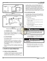
Figure 7
Blower Units Without In-Place Cleaning
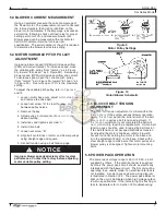
Figure 8
Blower Units With In-Place Cleaning

