Service and Parts Manual
52
(
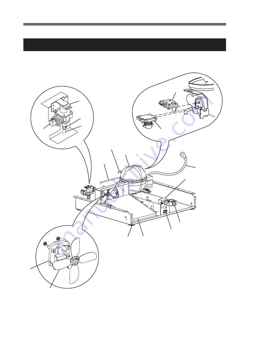
COMBO 75A MANUAL DEFROST HYBRID (2 OF 2)
Serial Numbers
U-Combo 75A 2004 Design
6
3
5
4
11
10
9
7
8
13
12
14
15
16
17
2
1
CO75A_002
Page 1: ...PO Box 245040 Milwaukee WI 53224 9540 U Line Corporation 8900 North 55th Street Milwaukee WI 53223 SERVICE AND PARTS MANUAL Models 95 Icemaker 98 Icemaker BI15 Icemaker 15R 15 Wine Captain Combo 75 F...
Page 2: ...ot approved the process of converting a CFC 12 system to any other type of refrigerant POTENTIAL PROBLEMS WITH HFC 134A HFC 134A compressors will be received with a synthetic based ester oil charge Th...
Page 3: ...16 Freeze Cycle 16 Harvest 1 Cycle Hold switch in normal position 16 Harvest 2 Cycle Hold switch in switched position 17 Water Fill Cycle 17 Temperature Control Specifications 18 Limit Switch Specific...
Page 4: ...ranty covers parts and labor for one year from the date of purchase plus four additional years for the compressor part only PRODUCTS SHIPPED AFTER 11 1 98 Warranty covers parts and labor for one year...
Page 5: ...htening damages incurred or resulting from shipping improper installation unauthorized modification or misuse abuse of the product customer education calls food loss spoilage door and water level adju...
Page 6: ...serious injury DANGER WARNING indicates a potentially hazardous situation which if not avoided could result in death or serious injury CAUTION indicates a potentially hazardous situation which if not...
Page 7: ...ring cutting of power cord removal of power cord removal of power plug or direct wiring can cause serious injury fire and or loss of property and or life and will void the warranty DANGER Do not lift...
Page 8: ...please supply the model and serial number of both units the unit being replaced and the new unit and the R A number If a copy of the Proof of Purchase Install is not available at the site the technic...
Page 9: ...an U Line s warranty does not cover cleaning the condenser Is the unit behind closed doors The unit must have free air flow to the front grille Did you try turning the temperature control colder Turni...
Page 10: ...rs Manual Defrost Combo 75A Combo 29A 95 98 75 BI15 Cycle Defrost 75R 29R 15R 75WC 29WC 15WC BC85DT Auto Defrost 29AD 75AD 75 Bev periodic manual defrost may be needed Frost Free Combo 75FF Combo 29FF...
Page 11: ...reduction of pressure on the liquid refrigerant causes it to boil or vaporize until it reaches saturation temperature As the low temperature refrigerant passes through the evaporator coil it continues...
Page 12: ...rough capillary tube Normal vapor compression cycle refrigeration Defrost Mode Bypass solenoid valve open Refrigerant flows through bypass system Vapor flows from condenser to evaporator without a pha...
Page 13: ...Specifications EMI3OHER Start Winding Resistance 28 OHMS EMI3OHER Run Winding Resistance 8 OHMS SD39 Start Winding Resistance 11 OHMS SD39 Run Winding Resistance 5 OHMS EMI5OHER Start Winding Resistan...
Page 14: ...perature Outlet below room temperature Partial Somewhat Warm near Very hot Top passes Room Extremely cold Lower than Restriction lower than room warm temperature near inlet normal normal in temperatur...
Page 15: ...s reach approximately 2 00 position and cam depresses the hold switch Power goes through the hold switch to the ice maker motor and mold heater B Ejector blades stall on ice and ice maker motor pulsat...
Page 16: ...ue black CONTROL TEMP NC black orange 3 yellow 2 orange SWITCH BIN red NO 1 C NO brown black white C SWITCH HOLD VALVE WATER ground UL183 5 FREEZE CYCLE SWITCH LIMIT orange black black black MOTOR MAK...
Page 17: ...2 orange SWITCH BIN red NO 1 C NO brown black white C SWITCH HOLD VALVE WATER ground UL183 7 HARVEST 2 CYCLE Hold Switch In Switched Position SWITCH LIMIT orange black black black MOTOR MAKER ICE MOL...
Page 18: ...After ice is sensed in the mold the 2 3 contacts open stopping the compressor and the 2 1 contacts are closed starting the ice maker motor The 2 3 contacts close 2 1 contacts open before the end of th...
Page 19: ...Degrees F The function of this switch is to open in the event of an overheating condition This bi metal thermostat is normally closed and does not initiate the ice harvest cycle The ice harvest cycle...
Page 20: ...ailure Water Adjustment Bin Switch Failure NO NO EVERYWHERE INTERMITTENT AT 3 00 YES NO AT 12 00 DOES THE UNIT HARVEST ICE IF THE EJECTOR BLADES ARE MOVED BY HAND OR WITH A WRENCH WHERE DO THE EJECTOR...
Page 21: ...compressor a Matsushita Model SD39C replaces the previous compressor an Embraco EMI 50 HER Both the previous design and the new redesign are detailed in this manual New design units and previous desi...
Page 22: ...At Evaporator Blade Air Flow Out At Evaporator Outlet Air Passes Through Fin Tube Evaporator Condensate Drains Down Trough Under Evaporator Into Drain Cup And Into Condensate Pan Through Drain Hose Th...
Page 23: ...sconnect fan wires in the back of unit 2 Remove fan blade by sliding off fan motor shaft 3 Remove screws 2 from fan motor mount ing bracket 4 Remove mounting nuts 2 from fan motor studs To remove evap...
Page 24: ...r 1 Disconnect fan wires in the back of unit 2 Remove fan blade by sliding off fan motor shaft 3 Remove screws 2 from fan motor mount ing bracket 4 Remove mounting nuts 2 from fan motor studs To remov...
Page 25: ...wires in the back of unit 2 Remove fan blade by sliding off motor shaft 3 Remove screws 2 from mounting bracket 4 Remove nuts from fan motor studs To remove evaporator 1 Recover all refrigerant 2 Dis...
Page 26: ...place water switch Solenoid valve defective Replace solenoid valve Fill tube outlet frozen Replace solenoid valve and defrost fill tube Broken wire in water fill circuit Repair or replace wiring 3 Wil...
Page 27: ...epair or replace wiring Power cord not plugged in Plug in power cord On Off switch in off position Put switch in on position Ejector blades not in the freeze Manually advance ejector blades to the pos...
Page 28: ...mounting or shroud Fan blade obstruction wiring foam Remove obstruction insulation packaging material 16 Ice build up in drain trough or drainage problem see page 20 Cause Remedy Obstructed drain cup...
Page 29: ...OL B42061 eps BLACK POWER CORD ASSEMBLY GREEN GROUND BLACK HOT SMOOTH BLACK NEUTRAL RIBBED ROCKER SWITCH BLACK RED YELLOW BROWN WHITE WATER VALVE BLACK BLACK 3 RPM MOTOR LIMIT SW MOLD HEATER C NO NC B...
Page 30: ...O COMBO 75A 220 VOLT WIRING DIAGRAM WITH BASE MOUNTED CONTROL P N 41886 N O ICEMAKER ASSEMBLY BLACK LOAD OVER COMPRESSOR GREEN BLACK BLACK WHITE GREEN ON OFF SWITCH RELAY CONDENSER BLACK WHITE FAN BLA...
Page 31: ...EN CAPACITOR BLUE WHITE BLUE COMPRESSOR 8 RELAY 3 OVERLOAD BLUE RELAY OVERLOAD 2 ASSEMBLY POWER CORD Compressor Junction Molded WHITE NEUTRAL GREEN BLACK HOT RELAY OVERLOAD Fan Control BLACK BLACK MOT...
Page 32: ...GRAM D42062 eps BLACK POWER CORD ASSEMBLY GREEN GROUND BLACK HOT SMOOTH BLACK NEUTRAL RIBBED ROCKER SWITCH BLACK RED YELLOW BROWN WHITE WATER VALVE BLACK BLACK 3 RPM MOTOR LIMIT SW MOLD HEATER C NO NC...
Page 33: ...LACK WHITE WHITE OVERLOAD BLUE CONTROL TEMP COMPRESSOR BROWN WHITE WHITE MOTOR TIMER DEFROST 3 1 2 4 BLACK FAN CONDENSER BLACK P N B41870 A42058 eps LAMP FAN CONTROL BLACK BLACK POWER CORD ASSEMBLY GR...
Page 34: ...BIN ORANGE BROWN C C MOTOR 3 RPM ORANGE BLACK ORANGE N O C SW HOLD N C NO SW WATER CAM NC BLACK NO RED NC BLUE WHITE BLUE GREEN BLUE CAPACITOR WHITE RELAY COMPRESSOR OVERLOAD BLACK OVERLOAD RELAY 8 3...
Page 35: ...TEMP BLACK BLACK BLACK LAMP SWITCH DOOR BLACK WHITE EVAPORATOR BROWN BLACK GREEN WHITE FAN COMPRESSOR OVERLOAD BLUE RELAY GREEN WHITE WHITE BLACK TIMER DEFROST P N 41926 RIBBED WHITE GREEN HOT NEUTRAL...
Page 36: ...ER NC ORANGE NO SW BIN C RED BLACK WHITE BLUE CAPACITOR BLUE BLUE GREEN WHITE COMPRESSOR 3 BLACK OVERLOAD RELAY OVERLOAD RELAY 2 8 P N A41882 WHITE RIBBED MOTOR BLACK SOLENOID BYPASS TIMER BLACK WHITE...
Page 37: ...WHITE GREEN MATSUSHITA GREEN BLACK BLUE WHITE BLACK RELAY OVERLOAD COMPRESSOR P N 41968 COMBO 75FF New Design starting S N 7CF600000 WIRING DIAGRAM BLACK WHITE RIBBED BLACK SOLENOID BYPASS TIMER BLAC...
Page 38: ...D 15WC 75WC ONLY RELAY RELAY NEUTRAL WHITE NEUTRAL WHITE HOT BLUE HOT BLUE DANFOSS COMPRESSOR EMBRACO COMPRESSOR 15WC 29WC 75WC 75 BEV WIRING DIAGRAM WHITE NEUTRAL NEUTRAL WHITE WHITE Fan BLUE Control...
Page 39: ...mpressor Ice Makers 5404 S 5411 Overload 5415 5412 Relay 5416 150 Faceplate Ass y 650 5400 S Compressor Wine Captains 5403 S 5414 Relay 5418 5413 Overload 5417 Parts used on models 95 98 Ice Makers an...
Page 40: ...21 29 30 10 11 7 9 4 5 28 8 24 22 6 31 23 3 2 1 402ICEMAKER Use only genuine U Line replacement parts U Line ice maker parts are not the same as standard FSP Whirlpool parts Using non U Line parts can...
Page 41: ...eater 625843 S 625843 S 625843 S 17 Stripper 31400 31400 31400 18 Stripper Screw 489128De 489128Description 489128 Part No 19 Mold Heater Assembly 628123 S 628123 S 628123 S 20 Water Cup 544304 544304...
Page 42: ...1492 14 Switch On Off 2053 15 Lamp Bulb 31317 16 Ice Bin Door 31523 S Item Description Part No 17 Glass Shelf 1 31427 1 18 Glass Half Shelf 1 31435 19 Grille 11664 20 Glass Short Shelf 2 31423 1 21 Tr...
Page 43: ...er 5188 12 Condenser 1951 FFS 13 Back Panel 11769 Item Description Part No 16 Power Cord 2242 17 Solenoid Valve 2552A 18 Compressor 5405 FFS 19 Relay Overload 5421 21 Bypass Valve Ass y 2749 S 24 Drai...
Page 44: ...cket 31501 12 Control 2717 13 Control Knob 41492 14 Switch On Off 2053 15 Lamp Bulb 31317 16 Ice Bin Door 31523 S Item Description Part No 17 Glass Shelf 1 31427 1 18 Glass Half Shelf 1 31435 19 Grill...
Page 45: ...Dryer 2692 6 Fan Motor Condenser 5300 7 Fan Blade Condenser 5428 8 Condenser 1951 FFS 9 Back Panel 11769 Item Description Part No 10 Power Cord 2318 11 Solenoid Valve 2552A 12 Compressor 5405 FFS 13...
Page 46: ...Complete Door Ass y 29 DOOR 12 Control 2717 13 Grille 11663 14 Ice Bin Door 31523 S Item Description Part No 15 Glass Shelf 2 Short 31425 1 16 Switch On Off 2053 17 Ice Bin Door Hinge 2 31463 18 Shel...
Page 47: ...18 Back Panel 11545 1 Item Description Part No 19 Power Cord 2317 20 Solenoid Valve 2552A 22 Relay Overload 5421 24 Compressor 5405 FFS 25 By Pass Valve Ass y 2749 S 28 Drain Pan 31550 1 F 29 Capacit...
Page 48: ...cket 31501 12 Complete Door Ass y 29 DOOR 13 Control 2717 14 Grille 11663 15 Ice Bin Door 31523 S Item Description Part No 16 Glass Shelf 2 Short 31425 1 17 Switch On Off 2053 18 Ice Bin Door Hinge 2...
Page 49: ...13 Dryer 2692 15 Fan Motor Condenser 5300 16 Fan Blade Condenser 5428 18 Back Panel 11545 1 Item Description Part No 19 Power Cord 2317 20 Solenoid Valve 2552A 22 Relay 5421 24 Compressor 5405 FFS 25...
Page 50: ...Service and Parts Manual 50 COMBO 75A MANUAL DEFROST HYBRID 1 OF 2 Serial Numbers U Combo 75A 2004 Design 14 12 15 13 16 8 9 7 10 11 6 5 4 3 1 2 17 18 19 20 21 22 23 CO75A_001...
Page 51: ...lf Narrow 40002 40002 11 Front Edge Trim 31443 8 31443 8 12 Top Hinge Assembly 11849 ST BLK 242 1 SS 13 Top Pivot Screw 41785 SSB N A 14 Bottom Hinge Assembly 11849 SB BLK 245 1 SS 15 Bottom Pivot Scr...
Page 52: ...Service and Parts Manual 52 COMBO 75A MANUAL DEFROST HYBRID 2 OF 2 Serial Numbers U Combo 75A 2004 Design 6 3 5 4 11 10 9 7 8 13 12 14 15 16 17 2 1 CO75A_002...
Page 53: ...254 41254 6 Water Valve 2552A 2552A 7 Dryer 2694 2694 8 Evaporator Heat Exchanger 74000 75 29 74000 75 29 9 Compressor Assembly 5402 S 5402 S 10 Relay 5414 5414 11 Overload 5413 5413 12 Power Cord 291...
Page 54: ...402 11 Ice Bucket 31501 12 Control 2763 13 Control Knob 41492 14 Switch On Off 2053 Item Description Part No 15 Lamp Holder NLA 16 Lamp Bulb 31317 17 Ice Bin Door 31523 S 18 Glass Shelf 1 31427 1 19...
Page 55: ...Feet 4 41319 5 Dryer 2694 6 Evaporator Heat Exchanger 2189 75 7 Fan Motor 5263 8 Fan Blade 5188 Item Description Part No 9 Condenser 1951 S 10 Back Panel 11769 11 Power Cord 1855 1 12 Solenoid Valve 2...
Page 56: ...ce and Parts Manual 56 COMBO 29A MANUAL DEFROST HYBRID Serial Numbers U Combo 29A 2004 Design 2 3 4 5 6 7 8 9 10 11 12 13 14 15 16 18 17 19 30 27 29 28 36 35 26 25 31 32 33 24 20 21 22 23 34 1 CO29A C...
Page 57: ...17031 02 80 17014 01 15 Shelf Retainer Rivet 41824 41824 16 Door Shelf Retainer 31521 2 31521 2 17 Bottom Hinge Assembly 11696 S KIT 11695 S BLK 18 Bottom Pivot Screw 41747 SSS 41747 SSB 19 Grille 11...
Page 58: ...Ice Maker Ass y 402 9 Ice Bucket 31501 10 Complete Door Ass y 29 DOOR 11 Control AR 19 12 12 Grille 11663 Item Description Part No 13 Ice Bin Door 31523 S 14 Glass Shelf 2 Short 31425 1 15 Switch On...
Page 59: ...41254 4 Cabinet Foot 4 41125 5 Dryer 2694 6 Evaporator Heat Exchanger 2189 29 7 Fan Motor 5263 Item Description Part No 8 Fan Blade 5188 9 Back Panel 11545 1 10 Power Cord 1855 1 11 Solenoid Valve 255...
Page 60: ...asket 31493 1 4 Pivot Hinge Top 11697 ST 5 Pivot Hinge Bottom 11695 S 7 Grille 11662 8 Condenser Ass y 2628 S Item Description Part No 9 Ice Maker Ass y 402 10 Ice Bucket 31429 11 Inner Liner Ass y Ev...
Page 61: ...mpressor 5401 S 5 Capacitor 5420 8 Cabinet Feet 4 41125 9 Dryer 2694 Item Description Part No 10 Fan Motor 5263 11 Fan Blade 5188 13 Back Panel Formed 11444 14 Power Cord 1855 1 15 Insulator Tube Arma...
Page 62: ...asket 31493 2 4 Pivot Hinge Top 11697 ST 5 Pivot Hinge Bottom 11695 S 7 Grille 11661 8 Condenser Ass y 2628 S Item Description Part No 9 Ice Maker Ass y 402 10 Ice Bucket 31430 11 Inner Liner Ass y Ev...
Page 63: ...eve Ass y 41254 4 Compressor 5401 S 5 Capacitor 5420 6 Cabinet Feet 4 41125 7 Dryer 2694 Item Description Part No 8 Fan Motor 5263 9 Fan Blade 5188 10 Solenoid Valve 2552A 11 Back Panel Formed 11443 1...
Page 64: ...ndle 31489 2 3 Door Gasket Lower 31606 4 Pivot Hinge Top 11697 ST 5 Pivot Hinge Bottom 11695 S 7 Grille 31543 8 Condenser Ass y 2223 S 9 Ice Maker Ass y 402 Item Description Part No 10 Ice Bucket 3143...
Page 65: ...3 Plastic Nut Sleeve Ass y 41254 4 Compressor 5402 S 5 Overload 5413 6 Cabinet Feet 4 41319 7 Dryer 2694 Item Description Part No 8 Fan Motor 5263 9 Fan Blade 5188 10 Solenoid Valve 2552A 11 Back Pan...
Page 66: ...1870 7 Condenser Ass y 2258 S 8 Ice Maker Ass y 402 9 Ice Bucket 31429 10 Inner Liner Ass y Evaporator 2182 S18 Item Description 11 Complete Door Ass y White WHT95M DR Complete Door Ass y Black 95 DOO...
Page 67: ...Sleeve Ass y 41254 4 Compressor 5402 S 5 Overload 5413 6 Relay 5414 7 Cabinet Feet 41125 8 Dryer 2694 Item Description Part No 9 Fan Motor 5263 10 Fan Blade 5188 11 Back Panel 11811 12 Power Cord 226...
Page 68: ...ss y 2749 S 19 Glass Half Shelf 1 31435 20 Door Ass y 75 DOOR 21 Evaporator Fan 5299 1 Item Description Part No 22 Evaporator Fan Blade 31656 23 Back Panel 11769 24 Timer 68000 25 Pivot Screw Top 4178...
Page 69: ...e Top 4 Hole 242 1 14 Hinge Bottom RH Top LH 245 Hinge Bottom 4 Hole 245 1 15 Door Gasket 31493 4 Item Description Part No 16 Door Handle 41984 3 17 Compressor 5400 S 18 Glass Half Shelf 1 31435 19 Do...
Page 70: ...12 Door Shelf Retainers 3 31521 1 13 Compressor 5402 S 14 Shelf Retainer Rivet 6 41824 Item Description Part No 15 Door Ass y 75 DOOR 16 Overload 5413 17 Pivot Screw Bottom 41747 SS 18 Back Panel 117...
Page 71: ...489 4 17 Door Shelf Retainers 3 31521 1 18 Compressor 5400 S Item Description Part No 19 Shelf Retainer Rivets 6 41824 20 Door Ass y 75 DOOR 22 Overload 5411 23 Back Panel 11769 24 Trim Strips Front L...
Page 72: ...44 13 6 Door Gasket 31493 4 GRY 7 Bottom Door Hinge 245 1 SS 8 Door Switch Bracket 11712 9 Door Switch 1916 10 Rocker Switch 2053 11 Grille 11664 12 Control 2923 Item Description Part No 13 Condenser...
Page 73: ...49 S 19 Glass Half Shelf 1 31435 20 Door Ass y 75 DOOR Item Description Part No 22 Overload 5411 23 Back Panel 11769 24 Timer 2632 1 25 Pivot Screw Top 41785 26 Dryer 75AD 2692 27 Fan Motor 5263 28 Fa...
Page 74: ...lf Retainer Short 1 31521 3 16 Compressor 5400 S 17 Relay 5412 Item Description Part No 18 Door Ass y 29 DOOR 19 Back Panel 11545 1 20 Dryer 2693 21 Fan Motor 5263 22 Fan Blade 5188 23 Power Cord 2314...
Page 75: ...1695 S 16 Compressor 5400 S 17 Relay 5412 Item Description Part No 17 Relay 5412 18 Door Ass y 29 DOOR 19 Back Panel 11545 1 20 Dryer 2693 21 Fan Motor 5263 22 Fan Blade 5188 23 Power Cord 2234 24 Eva...
Page 76: ...ght 1847 2 S 17 Compressor 5400 S 18 Relay 5412 Item Description Part No 18 Relay 5412 19 Door Ass y WC29 DOOR 20 Back Panel 11545 1 21 Dryer 2694 22 Fan Motor 5263 23 Fan Blade 5188 24 Power Cord 231...
Page 77: ...SS 15 Door Ass y 15R DOOR 16 Door Handle 31489 2 17 Door Gasket 31493 6 Item Description Part No 18 Shelf Retainer Rivet 6 41824 20 Control 2766 S 21 Door Switch Plunger 1916 22 Lamp Cover 31314 23 L...
Page 78: ...Pivot Hinge Bottom 1847 2 S 15 Door Ass y 15WC DOOR 16 Door Handle 41984 1 17 Door Gasket 31493 6 Item Description Part No 18 Lock Ass y 41734 S 20 Control 2767 S 21 Door Switch Plunger 1916 22 Lamp O...
Page 79: ...rned a prepaid shipping label will be included with your new replacement part When returning parts please enclose a copy of your packing list and a copy of your labor claim showing the model and seria...
Page 80: ...__________ Phone ________________________________________ Fax __________________________________________ PART COLOR QTY DESCRIPTION MODEL SERIAL UNIT IN NUMBER WARRANTY SPECIAL INSTRUCTIONS All part s...
Page 81: ......
Page 82: ...P O Box 245040 Milwaukee WI 53224 9540 Phone 414 354 0300 FAX 414 354 7905 Printed in U S A P N 41921 2 05...