background image

PAGE 6 OF 30 

0318 IH-7259

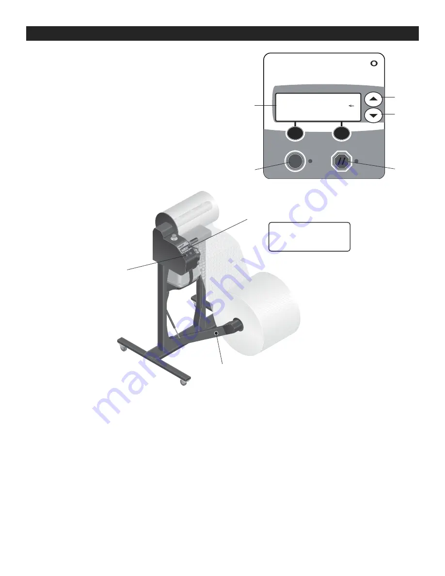
PRODUCING AIR-FILLED MATERIAL IN 

ROLL WINDER MODE

1.  Press winder release button to lower roll winder.

2.  Set the roll diameter.

•  Press and hold the up/down arrows for five seconds 

to enter operator's menu.

•  Scroll to Menu 2 Roll Size.
•  Using the up/down arrows, set the diameter from 

20-40" in 2" increments.

•  Press SELECT.
•  Press reset (//) to return to the ready window.

3.  Create a three-foot length of inflated material.

•  Using the start key, create a three-foot length of 

inflated material.

•  Using the stop key, stop the system.

4.  Slide the leading edge of inflated material into 

winder slot.

5.  Start the roll winder.

•  Toggle the winder start button to start/stop roll winder.

6.  Remove the finished roll of inflated material.

•  The winder will automatically stop once the roll 

reaches the programmed diameter.

•  Tear at a perforation and slide the roll off of winder.

OPERATION

OPERATOR MENU

Roll Size 

37"

˿

 D37

SAVE

CANCEL

Operator's

Menu

Roll Winder 

Button

Start Key

PRODUCING AIR-FILLED 

MATERIAL IN BATCH MODE

1.  Press up/down arrows to enter operator's menu.

•  Select Batch Mode.

2.  Adjust the batch length.

•  Using the up/down arrows, set the batch length in 

feet.

3.  Press the start key.

•  Press the start key to begin batching.

•  Press the stop key to pause batching.


READY

#1 A167PT

Batch Size

19

Screen

Up  

Arrow

Down  

Arrow

Start

Key

Stop

Key

Summary of Contents for H-7259

Page 1: ... sealing WARNING Hot Surface Edge seal roller will become hot during use WARNING Do not use bubble material as a flotation device toy or pillow NOTE User must set up and select film type before first usage See Film Code Settings on page 5 4 Inspect at regular intervals to ensure that Component cables are not cut broken or damaged All controls and indicators function properly 5 Airborne Noise Emiss...

Page 2: ...e Type NEMA 5 15R A C Voltage 100 120 VAC 50 60 Hz Phase Single Phase Grounded Current 15A Service 4 0A NOTE The use of non compatible materials will cause production problems may damage the equipment and will reduce the quality of the packaging protection 1 ON OFF Power Switch Switch controls power to system and is located on back of machine 2 Emergency Stop Switch E Stop Switch stops all feeding...

Page 3: ...lining rubber feet on the pump up with holes in the tray kit 6 Facing the front of the machine thread the power cord for air pump into the right circular hole on tray kit 7 Secure both ends of the hook and loop strip together to secure the air pump to tray kit See Figure 5 8 Attach rubber air hose to both the valve on the air pump and the valve under the fill tube Secure with zip ties to hold in p...

Page 4: ...new material roll so that the open end is facing towards the control panel Slide the roll fully onto the mandrel so that the end of the core is contacting the collar 2 Feed the material into the system See Figure 10 Lower the clamp handle to open the edge seal assembly Thread the material under the black directional roller Spread the open end of the material and wrap around the inflation nozzle be...

Page 5: ... same time to access the menu See Figure 12 2 Use the arrow buttons to move the cursors on either side of the screen to Engineering Press the select button on the left to select Engineering See Figure 13 FILM CODE SETTINGS ITEM NO DIMENSIONS FILM CODE S 19738 Medium Premium 1 2 inflated 12 x 2 050 Perf 12 A1S7LJ S 19739 Medium Premium 1 2 inflated 24 x 2 050 Perf 12 A1T7HT S 19740 Large Premium 3 ...

Page 6: ... inflated material into winder slot 5 Start the roll winder Toggle the winder start button to start stop roll winder 6 Remove the finished roll of inflated material The winder will automatically stop once the roll reaches the programmed diameter Tear at a perforation and slide the roll off of winder OPERATION OPERATOR MENU Roll Size 37 D37 SAVE CANCEL Operator s Menu Roll Winder Button Start Key P...

Page 7: ... edge seal by twisting counter clockwise See Figures 17 and 18 3 Pull the edge seal wheel away from black plastic gear See Figure 18 4 Install the new edge seal Align the three connection pins on new wheel with the three receptacle holes in seat NOTE The hole pattern and pins are in a keyed pattern By hand thread the edge seal clockwise until tight Do not load film Raise the clamp handle to close ...

Page 8: ...red 07 Edge Seal Fault Edge seal wheel is missing or not fully seated Edge seal failure Check condition of edge seal and verify that it is fully seated Replace as required see Replacing the Edge Seal on page 7 Contact Uline Customer Service PROBLEMS WITH MAKING INFLATED MATERIAL PROBLEM CAUSES RECOMMENDATIONS The material will not advance the control panel is on Material roll is empty Material rol...

Page 9: ...e edge seal see Replacing the Edge Seal on page 7 Contact Uline Customer Service The inflated material leaks air Material roll improperly loaded Faulty edge seal The operator is pulling the inflated material directly out of the system before the inflated material can cool Faulty material Seal power out of adjustment Electrical or mechanical failure Reload material see Loading the Material Roll on ...

Page 10: ...r is not plugged in Obstruction blocking the winder or the roll Electrical or mechanical failure Press the winder start button see Producing Air Filled Material in Roll Winder Mode on page 6 Verify that the roll winder is plugged in to the bottom of the machine Verify the roll can wind free of obstruction Contact Uline Customer Service The roll is a different diameter than expected The diameter se...

Page 11: ...Superficie Caliente El borde del rodillo de la selladora se calentará durante el uso ADVERTENCIA No utilice el material de burbuja como equipo para flotar juguete o almohada NOTA El usuario debe configurar y seleccionar el tipo de película antes de su uso por primera vez Vea Configuraciones de los Códigos de la Película en la página 15 4 Inspecciónelo a intervalos regulares para asegurar que Los c...

Page 12: ... 50 60 Hz Fase Puesta a Tierra de Una Sola Fase ACTUAL Servicio 15A de 4 0A NOTA El uso de materiales no compatibles causará problemas de producción puede dañar el equipo y reducirá la calidad de la protección del embalaje 1 Interruptor ON OFF El interruptor controla la energía al sistema y está localizado en la parte posterior de la máquina 2 Interruptor de Freno de Emergencia E Stop El interrupt...

Page 13: ...4 Coloque la bomba de aire en la parte posterior de la charola detrás de la máquina alineando las patas de caucho en la bomba con los orificios en el kit de la bandeja 6 Viendo la parte frontal de la máquina pase el cable de alimentación de la bomba de aire por el orificio circular derecho del kit de charola 7 Asegure ambos extremos de la tira de gancho y felpa para asegurar la bomba de aire al ki...

Page 14: ...borde 3 Cierre la manija y haga algunos metros de material inflado de acojinado Vea Diagrama 11 Mientras mantiene la tensión en el material eleve la manija de sujeción para cerrar el ensamble del sello del borde NOTA Si el material no infla y o sella después de 20 cm vuelva a alimentar el material Vea el paso dos CONTINUACIÓN DE LA CONFIGURACIÓN DEL SISTEMA MENÚ DEL OPERADOR Para ingresar al menú ...

Page 15: ...e las flechas hacia arriba o hacia abajo y el botón de reconfigurar al mismo tiempo para acceder al menú Vea Diagrama 12 2 Utilice las flechas para mover el cursor de la pantalla para Engineering Ingeniería Presione el botón de seleccionar a la izquierda para elegir Engineering Vea Diagrama 13 CONFIGURACIONES DEL CÓDIGO DE PELÍCULA ARTÍCULO NO DIMENSIONES CÓDIGO DE PELÍCULA S 19738 Mediana Premium...

Page 16: ... bobinadora para bajar la bobinadora 2 Establezca el diámetro del rollo Presione y sostenga las flechas hacia arriba y hacia abajo por cinco segundos para ingresar al menú del operador Desplácese al menú 2 Roll Size Tamaño del Rollo Usando las flechas hacia arriba y abajo configure el diámetro de 20 40 en incrementos de 2 Presione SELECT Presione reconfigurar para regresar a la ventana de READY 3 ...

Page 17: ...contrario a las manecillas del reloj Vea Diagramas 17 y 18 3 Tire de la rueda de sello del borde del engranaje de plástico negro Vea Diagrama 18 4 Instalación del nuevo sello del borde Alinee los tres pasadores de conexión en la rueda nueva con los tres orificios del receptáculo en el asiento NOTA El patrón de los orificios y pasadores están en un patrón enchavetado Con la mano pase el sello del b...

Page 18: ...ente 07 Edge Seal Fault Falta la llanta del sello del borde o no está completamente asentada Falla del sello del borde Verifique el estado del sello del borde y verifique que esté completamente asentado Reemplace adecuadamente Vea Reemplazo del Sello en el Borde en la página 17 Contacte a Servicio a Clientes de Uline PROBLEMAS AL HACER EL MATERIAL DE RELLENO PROBLEMA CAUSAS RECOMENDACIONES El mate...

Page 19: ...a eléctrica o mecánica Cargue un nuevo material Vea Carga del Rollo del Material en página 14 Verifique el estado del sello del borde en el material Verifique el estado del sello del borde y verifique que esté completamente asentado Reemplace adecuadamente Vea Reemplazo del Sello en el Borde en la página 17 No intente extraer material inflado de la máquina Cargue un nuevo material Vea Carga del Ro...

Page 20: ...e de obstrucciones Contacte a Servicio a Clientes de Uline El rollo es de un diámetro diferente al esperado La configuración del diámetro está configurada incorrectamente El rollo de material está vacío Falla eléctrica o mecánica Verifique la configuración del diámetro Vea Producción de Material de Relleno en Modo de Bobinado de Rollos en la página 16 Cargue un nuevo rollo apropiadamente Vea Carga...

Page 21: ... AVERTISSEMENT Surface chaude Le joint de bordure du rouleau devient chaud pendant l utilisation AVERTISSEMENT N utilisez pas la matière comme dispositif de flottaison jouet ou coussin REMARQUE L usager doit effectuer les configurations et sélectionner le type de film avant la première utilisation Voir Paramètres des codes de film à la page 25 4 Inspectez à intervalles réguliers pour vous assurer ...

Page 22: ...alternative 100 à 120 V c a 50 60 Hz Phase Courant monophasé à la terre Courant 15 A Service 4 0 A REMARQUE L utilisation d une matière non compatible entraînera des problèmes de production peut endommager l équipement et réduira la qualité de la protection de l emballage ARRÊT 1 Interrupteur d alimentation ON OFF marche arrêt L interrupteur contrôle l alimentation du système et est situé à l arri...

Page 23: ... la pompe à air à l arrière de l appareil en alignant les pieds en caoutchouc de la pompe à air sur les trous de l ensemble du plateau 6 En étant vis à vis de l appareil passez le cordon d alimentation de la pompe à air dans le trou circulaire droit de l ensemble du plateau 7 Joignez ensemble les deux extrémités de la sangle autogrippante pour fixer la pompe à air à l ensemble du plateau Voir Figu...

Page 24: ...tres des codes de film à la page 25 1 Installez le rouleau de matière sur le mandrin Voir Figure 9 Tenez le nouveau rouleau de matière de façon à ce que l extrémité ouverte soit orientée vers le panneau de commande Faites glisser entièrement le rouleau sur le mandrin afin que l extrémité soit appuyée contre sur le collet 2 Alimentez la matière dans l appareil Voir Figure 10 Abaissez la poignée du ...

Page 25: ...ion à gauche pour choisir Engineering Voir Figure 13 PARAMÈTRES DES CODES DE FILM N D ARTICLE DIMENSIONS CODE DE FILM S 19738 Moyenne de qualité supérieure 1 2 po gonflé 12 po x 2 050 pi perf 12 po A1S7LJ S 19739 Moyenne de qualité supérieure 1 2 po gonflé 24 po x 2 050 pi perf 12 po A1T7HT S 19740 Grande de qualité supérieure 3 4 po gonflé 12 po x 1 250 pi perf 12 po A124PT S 19741 Grande de qual...

Page 26: ...matériau gonflé dans la fente de la bobineuse 5 Démarrez la bobineuse Appuyez sur la touche de démarrage de la bobineuse pour démarrer arrêter celle ci 6 Retirez le rouleau fini de matériau gonflé La bobineuse s arrête automatiquement lorsque le rouleau atteint le diamètre prédéfini Déchirez à la perforation et retirez le rouleau de la bobineuse FONCTIONNEMENT Menu de l utilisateur Bouton de bobin...

Page 27: ...es composants sont refroidis avant de procéder 1 Abaissez la poignée du serre joint pour ouvrir le joint de bordure 2 Dévissez le joint de bordure en le tournant dans le sens antihoraire Voir Figures 17 et 18 3 Tirez sur la roue du joint de bordure pour la détacher de l engrenage en plastique noir Voir Figure 18 4 Installez le nouveau joint de bordure Alignez les trois broches de connexion de la n...

Page 28: ...her 03 Clamp Open Le serre joint est ouvert Soulevez la poignée du serre joint pour fermer le joint de bordure et appuyez sur la touche Réinitialiser 17 Check Film Path Il ne reste plus de film Le rouleau de matière n est pas chargé correctement Installez un nouveau rouleau Réinstallez le rouleau si nécessaire 07 Edge Seal Fault La roue du joint de bordure est manquante ou mal insérée Défaillance ...

Page 29: ...t correctement installé Remplacez au besoin voir Remplacement du joint de bordure Installez un nouveau rouleau voir Installation du rouleau de matière à la page 24 Retournez le rouleau de matière contactez le service à la clientèle de Uline Retirez réinstallez et calibrez le joint de bordure voir Remplacement du joint de bordure à la page 27 Contactez le service à la clientèle de Uline L air s éch...

Page 30: ... bobineuse n enroule pas le matériau gonflé La bobineuse est arrêtée La bobineuse n est pas branchée La bobineuse ou le rouleau sont obstrués Défaillance électrique ou mécanique Appuyez sur la touche de démarrage de la bobineuse voir Production de matériau rempli d air en mode bobineuse à la page 26 Vérifiez si la bobineuse est raccordée à la partie inférieure de l appareil Assurez vous que la bob...

Reviews: