background image

PAGE 3 OF 9 

0521 IH-5615

MAINTENANCE

Inspect gate for any permanent deformation, 

corrosion, degradation, failure of the gate to fully close 

automatically or any condition impairing protective 

capability.

DANGER! A fall resulting in DEATH or SERIOUS 
INJURY may occur if gate is improperly 
installed or used. If any of the conditions are 
suspected, barricade from use with warnings 
prohibiting use prominently displayed until 
gate can be replaced. 

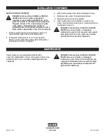
INSTALLATION CONTINUED

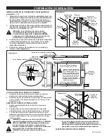
GATE WIDTH ADJUSTMENT

DANGER! A fall resulting in DEATH or SERIOUS 

INJURY may occur if gate is improperly 

installed or used. Gate width MUST be set for 

gate strike plate to overlap structure opposite 

the gate mount so the outside edge of gate 

strike plate is aligned past the center of 

guardrail tube, as illustrated in Figures 2 and 3. 

Gate width is adjustable in two inch increments. 

1.  Remove gate sleeve hex head cap screws and 

locknuts from gate sleeve and tube panel.

2.  Slide gate tube panel in or out to set position. 

Make sure the gate tube panel gate strike plate is 

positioned as shown in Figure 2.

3.  Align holes in gate tube panel and gate sleeve.

4.  Replace cap screws through aligned holes. 

5.  Replace locknuts and fully tighten.

6.  Open gate and let close. Make sure gate fully 

closes automatically and stops in closed position as 

illustrated in Figure 2.

DANGER! A fall resulting in DEATH or SERIOUS 
INJURY may occur if gate is improperly 
installed or used. Do not use gate unless gate 
tube panel and the cap screws are in place 
and locknuts are securely tightened.

1-800-295-5510

uline.com

Summary of Contents for H-5615

Page 1: ...at comply with OSHA 1910 ANSI A1264 and other applicable standards for guardrails Only install in applications where the top of the tube panel is 41 or higher Take necessary precautions during the mounting process Do not fully tighten mounting bolts until instructed to do so TOOLS NEEDED 7 16 Wrench 2 9 16 Wrench 3 4 Wrench 2 Rubber Mallet Safety Glasses Para Español vea páginas 4 6 Pour le frança...

Page 2: ...eration of gate trim bolt ends to approximately 1 4 from locknut with hacksaw or cut off wheel and deburr DANGER A fall resulting in DEATH or SERIOUS INJURY may occur if gate is improperly installed or used Gate must be installed to prevent unintended passage or fall into elevation change or other hazard Gate must not open toward elevation change or other hazard DANGER A fall resulting in DEATH or...

Page 3: ...t so the outside edge of gate strike plate is aligned past the center of guardrail tube as illustrated in Figures 2 and 3 Gate width is adjustable in two inch increments 1 Remove gate sleeve hex head cap screws and locknuts from gate sleeve and tube panel 2 Slide gate tube panel in or out to set position Make sure the gate tube panel gate strike plate is positioned as shown in Figure 2 3 Align hol...

Page 4: ...nstalación No apriete los pernos de instalación por completo hasta que se le indique INSTALACIÓN 1 Puerta 2 Barras de Torsión PARTES 2 Pernos en J 2 Pernos en U Redondos 4 Rondanas Planas de 3 8 4 Tuercas de Seguridad Hexagonales de 3 8 16 4 Tuercas Hexagonales de 1 2 13 2 Tornillos de Cabeza Hexagonal Paquete de Tornillería PERNOS DE INSTALACIÓN 2 Pernos en U Cuadrados HERRAMIENTAS NECESARIAS 2 L...

Page 5: ...as del perno a aproximadamente 6 3 mm 1 4 de la tuerca con una sierra o esmeril PELIGRO Si la puerta se instala o usa de forma incorrecta puede ocasionar una caída con LESIONES SERIAS o la MUERTE La puerta debe instalarse para prevenir el paso no deseado o caídas hacia el desnivel o algún otro peligro La puerta no debe abrir hacia el desnivel o cualquier otro peligro PELIGRO Si la puerta se instal...

Page 6: ...ubo del pasamanos como se muestra en los Diagramas 2 y 3 El ancho de la puerta se ajusta en incrementos de 2 pulgadas 1 Retire los tornillos de cabeza hexagonal y las tuercas de la manga de la puerta y del panel del tubo 2 Deslice el panel del tubo de la puerta hacia adentro o hacia afuera para fijar la posición Asegúrese de que el panel del tubo de la puerta y la placa de tope de la puerta estén ...

Page 7: ...es précautions nécessaires lors du procédé de montage Ne pas serrer les boulons de montage à fond avant d y être invité à le faire INSTALLATION PIÈCES Battant x 1 Boulon en U carré x 2 Boulon en J x 2 Boulon en U arrondi x 2 Rondelle plate de 3 8 po x 4 Écrou freiné hexagonal de 3 8 16 x 4 Écrou hexagonal de 1 2 13 x 4 Vis d assemblage à tête hexagonale x 2 Trousse de matériel BOULONS DE MONTAGE B...

Page 8: ...iron 6 3 mm 1 4 po de l écrou freiné à l aide d une scie à métaux ou d une meule tronçonneuse puis ébavurer DANGER Une chute pouvant causer la MORT ou des BLESSURES GRAVES peut se produire si le battant n est pas installé ou utilié correctement La barrière doit être installé pour interdire le passage ou pour prévenir toute chute de changement de hauteur ou tout autre danger Le battant ne doit pas ...

Page 9: ...té tubulaire du garde corps comme illustré sur les Figures 2 et 3 La largeur du battant est réglable par intervalles de 5 cm 2 po 1 Retirez les vis d assemblage à tête hexagonale et les écrous freinés du manchon de battant et de l extrémité tubulaire 2 Glissez l extrémité tubulaire vers l intérieur ou l extérieur pour régler sa position Assurez vous que l extrémité tubulaire et la plaque d arrêt d...

Reviews: