4-21
Section 4 - Parts
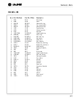
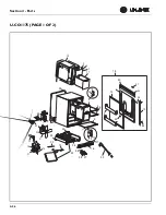
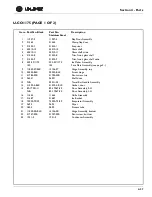
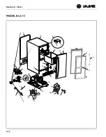
MODEL 29R
Item Part No. Black
Part No. White
Description
1
31391
31391
Drain trough
2
41885
41885
Screws
3
40010-08
40010-08
Glass shelf, no logo
4
25032-4
23052-4
Trim, rear, glass shelf
5
40010-07
40010-07
Glass shelf, with logo
6
11508
11508
Funnel drain cup
7
31578
31578
Washer, drain tube
8
31579
31579
Drain tube
9
11697-ST-BLK
11697-ST-KIT
Hinge Assembly, top
10
41893-BLK
41893-ZP
Screw, hinge
11
41747-SSB
41747-SSW
Pivot screw, top
12
31489-3-BLK
31489-3-KIT
Door handle
13
31493-3-GRY
31493-3-WHT
Gasket, door
14
29-DOORBLK
29-DOORKIT
Door Assembly
15
31521-2
31521-2
Retainer, door shelf, long
16
31521-3
31521-3
Retainer, door shelf, short
17
80-29014-01
80-29014-02
Grille Assembly
18
1960-S
1960-S
Evaporator Assembly
19
2693
2693
Dryer
20
2800
2800
Process tube
21
11695-S-BLK
11695-S-KIT
Hinge Assembly, bottom
22
41785-SSB
41785-SSW
Pivot screw, bottom
23
1893-S
1893-S
Condenser Assembly
24
41125
41125
Foot, cabinet
25
31550-1-F
31550-1-F
Drain pan
26
5263-S
5263-S
Fan motor
27
5188
5188
Fan blade
28
2305
2305
Power cord
29
70077-S
70077-S
Compressor Assembly
30
71010
71010
Relay
31
71009
71009
Overload
32
71008
71008
Capacitor
33
2766
2766
Control
34
42003
42003
Screw, control
35
11545-1
11545-1
Back panel
Summary of Contents for BI95FCB
Page 9: ...1 8 Section 1 General Information This page intentionally left blank...
Page 27: ...3 12 Section 3 Service and Repair THIS PAGE INTENTIONALLY LEFT BLANK...
Page 29: ...4 2 Section 4 Parts U LINE ICE MAKER ASSEMBLY...
Page 61: ...4 34 Section 4 Parts This page intentionally left blank...
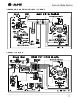
Page 63: ...5 2 Section 5 Wiring Diagrams U CO29A CO1175A BI2115 ADA15IM 115 VOLT ULN 29R 115 VOLT...
Page 64: ...5 3 Section 5 Wiring Diagrams 1075BEV 1075WC 115 VOLT...


