


NORA-W10 series - System integration manual
UBX-22005601 - R04
Module overview
Page 8 of 56
C1-Public
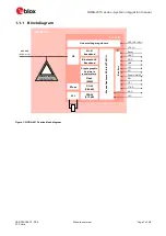
1.2
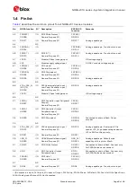
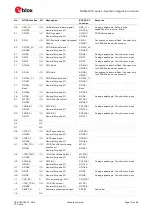
Pin definition
1.2.1
General Purpose Input and Output, GPIO pins
NORA-W101/NORA-W106 modules have 82 pins. 38 pins can be used for either input or output. 4 pins
are for input only.
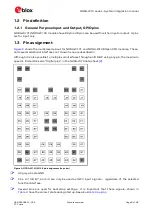
1.3
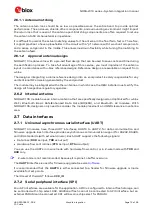
Pin assignment
shows the multiplexed pinout for NORA-W101 and NORA-W106 Open CPU modules. These,
and several additional interfaces not shown here, are described in
Although it is also possible to multiplex all interfaces through an IO MUX using any pin, the maximum
speed is limited. See also
“Digital pins” in the
NORA-W10 data sheet
Figure 2: NORA-W101/W106 pin assignment (top view)
☞
All grey pins are GND.
☞
Pins A7, A8, B7, and J3 can only be used as (GPI) input signals
–
regardless of the selected
function/interface.
☞
Several pins are used for bootstrap settings. It is important that these signals, shown in
have the correct state during startup. See also