NINA-B1 series - Getting Started
UBX-16009942 - R04
Configuration
Page 7 of 19
2.3
Client and server
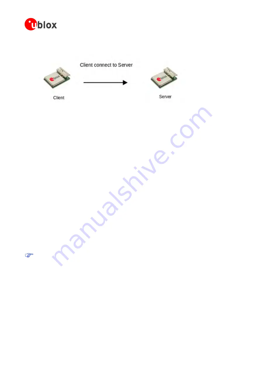
A client will initiate a connection and the server will accept an incoming connection.
Figure 2: NINA-B1 as a client connecting to the NINA-B1 server
To configure a client to automatically set up a connection to a server, configure the correct Bluetooth service and
the remote peer. The Bluetooth service controls the type of connection that is requested (see section 2.4) and
the preferred server to connect is defined by the remote peer.
•
Default Remote Peer
AT+UDDRP
Configures server (profile and address) to connect and when to
initiate the connection. Peer is enumerated starting with id 0.
•
Server Configuration
AT+UDSC
:
Will only accept incoming connection attempts for the configured
server profile. NINA-B1 will have the SPS enabled by default.
2.4
Bluetooth services
The Generic Attributes (GATT) is used when Bluetooth LE devices exchanges data. There are two roles defined in
GATT - the client and server. For more information about GATT, see [8].
The GATT server stores data received from the GATT client. The GATT server sends responses to requests and
sends indications and notifications to the GATT client when specified events occur on the GATT server.
Official as well as user defined GATT Services can be set up with AT commands. The Serial Port Service (SPS) is a
u-blox proprietary serial cable emulation service, which is enabled by default.
2.5
Command mode, Data mode, and Extended data mode
By default, NINA-B1 will enter command mode and has to be reconfigured to start up in data mode or extended
data mode. From the data mode or extended data mode, it is possible to enter the command mode by
transmitting escape sequence to the module. By default, the escape sequence is:
1.
Silence 1 second
2.
+++
3.
Silence 1 second
The +++ must be sent within 200 ms, which means that it is difficult or impossible to enter the
escape sequence manually using a terminal window though the characters can also be typically pasted
instead. The module leaves the command mode and enters data mode using the
ATO1/ATO2
command. It
is also possible to toggle the UART DTR pin from High to Low to enter the command mode.


