EVK-NINA-B50 - User guide
UBX-23007761 - R02
Board configuration
Page 16 of 37
C1-Public
Battery powered, 3
–
1.71 V
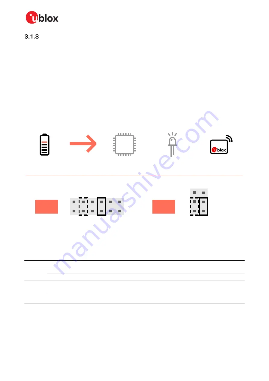
When using a battery,
shows the default configuration. The battery voltage is connected to
VDD_NINA
, which in turn, is connected to the NINA-B50 VCC supply. If needed, a jumper can be added
to J22, pins 2 and 4, to supply LEDs and other peripherals with power
–
as long as this does not exceed
the maximum current rating of the battery. If the NINA module must be configured, the
VDD_MCU
net can be connected to enable PC communications by adding a jumper to J7 pins 9 and 10.
☞
Jumpers must be connected to both J7: 9
–
10 and J22: 2
–
4 to be able to communicate with the
NINA module from a PC. If possible, the EVB power configuration should be switched to the
default 3.3 V configuration, as connecting an extra board peripheral might deplete the battery.
⚠
Less than 3 V voltage level at
VCC
and
VCC_IO
has negative impact on Tx output power.
⚠
Do not connect jumpers J7: 5
–
6 and J7: 7
–
8 at the same time while a battery is connected. This
might cause damage to the battery.
Figure 10: Jumper positions for battery powered operation - with optional jumpers shown as dashed lines
Connector
Add jumper to pins
Description
J7
5, 6
Selects the battery connected to the battery holder as source for the VDD_NINA net.
9, 10
(Optional) Powers up the Interface MCU, USB hub, and UART to USB converter with 3.3 V.
J22
1, 3
Powers up the NINA module. The NINA VCC and VCC_IO pins are connected to the
selected source for the VDD_NINA net.
2, 4
(Optional) Powers up the peripherals directly connected to NINA such as LEDs and
external memory with the NINA supply voltage.
Table 4: Jumper positions for battery powered operation
–
with two optional jumpers
J7
B
O
ARD
BA
TT
3V3
3
4
2
1
J22
V
C
C
_IO
V
C
C
5
6
9
10
NINA module power
board I/O power
(optional)
J22: 2-4
J22: 1-3
PC communication
(optional)
MCU
J7: 9-10
Battery powered
J7: 5-6


