EVA-M8E - Hardware Integration Manual
UBX-15028542 - R05
Appendix
Page 36 of 44
Production Information
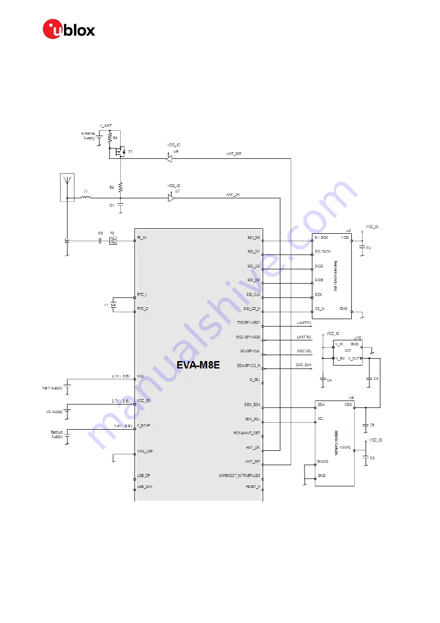
A.7
Circuit using 2-pin antenna supervisor
•
2-pin antenna supervisor
•
RTC crystal
•
Backup battery
•
UART and DDC for communication to host
Figure 20: Circuit using 2-pin antenna supervisor


