


TYM 1000/2000 Slide Gate Operator Installation Guide
- 22 -
Rev 9 02/14
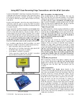
Dip Switch 6 – Delay Timing
: The default position is set to OFF. When switch 6 is in the ON position, a 2-second “detect” delay feature will delay
outputs A & B for a period of 2 seconds after a vehicle has entered the detection zone. Note that the DEFLECTOMETER will display the letter “d” for
“Delay Time”. If the vehicle does not remain in the loop zone for the full 2 seconds the delay will terminate and no DETECT output will be produced.
Dip Switch 7 – Output “A” Modes
: Output A has 2 selectable output modes: Infinite Presence and Normal Presence. The default position is Infinite
Presence (switch 7 = OFF). In the Infinite Presence mode, a presence output will always be maintained as long as a vehicle is over the loop and
power is not removed for more than approximately 3 seconds. In the Normal Presence mode (switch 7 = ON), the output hold time is between 5
minutes minimum and 3 hours maximum. Hold time depends on loop geometry; number of wire turns in the loop, vehicle size, and position of the
vehicle relative to the loop.
Dip Switch 8 – Sensitivity Boost
: The default position is set to OFF. When switch 8 is in the ON position and when a vehicle enters the loop zone,
the detector sensitivity is boosted to a higher level than the vacant loop setting. The boosted sensitivity remains throughout the DETECT period.
When the vehicle leaves the loop zone, the sensitivity returns to the vacant loop setting. This feature is designed to automatically increase sensitivity
only during the DETECT output period. This feature aids in preventing dropouts during the passage of high bed vehicles and is particularly useful in
sliding gate situations.
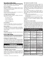
Detector Diagnostics
: The detector continuously checks the integrity of the loop. The system is able to detect open or shorted circuit loops, or
sudden changes in inductance exceeding 25% of the nominal inductance. If a fault is detected, the POWER and DETECT LED both continuously
emit a sequence of flashes. Additionally, the 7-Segment DEFLECTOMETER displays F1, F2, or F3 indicating a current loop fault. Each type of fault
is identified by a different flash sequence:
Flash Sequence
Deflectometer Display
Fault Condition
1 flash
F 1
Open Circuit Loop
2 flashes
F 2
Shorted Circuit Loop
3 flashes
F 3
25% excessive change in inductance
If the Open or Shorted fault condition self heals, the DETECT LED and 7-Segment DEFLECTOMETER will return to normal operation. Only the
POWER LED will continue to flash with the sequence signifying the type of fault that was last detected. In the case of the excessive inductance
change (F3) fault, the unit will retune to the new inductance after a period of two seconds and continue operation. The previous fault condition will be
indicated by the flash sequence of the only POWER LED. Pressing the “Reset” button will reset the detector and clear the flash sequence from the
POWER LED. If you want to review the last loop fault condition, simply press and hold the “Reset” button for 2 seconds and the DETECT LED will
display the previous loop fault condition.
Pin Assignments
:
Pin
Function
Pin
Function
1
Loop
6
Output B
2
Loop
7
Output B Inverted
3
Power (12-24VDC, 24Vac)
8
Output A (Presence Output)
4
No Connection
9
Power (12-24VDC, 24Vac)
5
No Connection
10
Common
Note: Power may be applied on either pin 3 or 9, or both