III. MULTIBAND
™
FEATURE
• Your vehicle features the advanced Tyco® R/C MultiBand™
system. This system lets you race your vehicle head-to-head
– against up to two of your friends (up to 3 drivers total) –
without any radio interference from your friends’ transmitters
or vehicles.
You must be racing against another Tyco® R/C
MultiBand™-equipped vehicle for this feature to work.
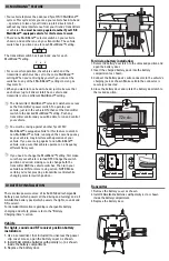
• There’s one MultiBand™ selector switch on your vehicle
chassis, and another one on your transmitter. The vehicle
switch has 3 positions: one for each MultiBand™ setting.
The transmitter switch has 3 positions: one for each
MultiBand™ setting.
• For successful operation, the vehicle switch and the
transmitter switch must be set to the same MultiBand™
setting. When you’re driving by yourself, you can set the
switches to any of the 3 MultiBand™ settings (as long as
they match).
• When you want to race head-to-head, just make sure that
each driver (up to 3 drivers total) has a vehicle and
transmitter set to a different MultiBand™ setting.
*
The transmitter’s MultiBand™ selector switch also serves
as the transmitter’s power switch. To operate your
vehicle, just turn the vehicle ON; then set the transmitter
switch to the desired MultiBand™ setting. Push any
transmitter control and you will be able to run and control
your vehicle.
*
You must be racing against another Tyco® R/C
MultiBand™-equipped vehicle for this feature to work. A
non-MultiBand™ vehicle, running on the same frequency
as your vehicle, may interfere with operation of your
vehicle. If you are racing against a non-MultiBand™
vehicle, make sure that vehicle operates on a frequency
different from yours.
*
If you need to change the MultiBand™ setting, first make
sure that your vehicle is turned OFF. Change the switch
position as desired, making sure to change both the
transmitter AND the vehicle switches. Then turn your
vehicle back ON for more racing action. NOTE: Make
certain you’re not pressing a transmitter control while
changing selector switch position.
1
2
3
Transmitter
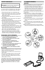
1. Remove the battery cover as shown.
2. Install 2 AA alkaline batteries with polarity (+/-) as shown
inside the battery compartment.
3. Replace the battery door.
There are two power sources: a 7.2v SubC NiCad rechargeable
battery pack (which powers all the driving and turning) and a 3
AA Alkaline battery pack (which powers the lights, sounds and
RF receiver).
For detailed information regarding rechargeable battery
charging and safety, please refer to the “Battery
Charging/Care” section.
Vehicle
For lights, sounds and RF receiver position battery
installation:
1. Use a screwdriver (not included) to unscrew the power
clip cover screw, open the battery cover as shown.
2. Install 3 AA alkaline batteries with polarity (+/-) as shown
inside the battery compartment.
3. Replace the battery door.
IV. BATTERY INSTALLATION
7.2 v d.c.
7.2 v d.c.
1 2 3
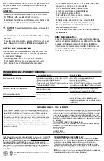
For driving battery installation:
1. Rotate the battery door latch to the unlocked position and
open the battery door.
2. Insert the charged battery pack into the battery
compartment as shown.
3. Connect the battery pack’s wire connector to the vehicle’s
charging jack as shown. Make certain the connector is
securely connected.
4. Close the battery door and rotate the battery door latch to
the locked position.
1
2
3
7.2v d.c.


