2/4
Fixing Instructions Doc. version 3
PRN800 MX Printer
MZX Fire alarm system
2 Remove the blanking plate and fit the
printer assembly.
3 Re-tighten blanking strips to secure
printer assembly.
4 Locate a spare cable entry gland into
the housing. If none is available, then
a knockout must be removed.
5 To remove a knockout, remove any
fouling PCBs (or wiring) to prevent
swarf or metal filings damaging them.
6 Holes for the cable entry gland must
be drilled in the T2000/T2000 battery
housing gland plates.
7 Connect data lead to printer assem-
bly. Data cable should be connected
to COM1 on FIM inside the MX/
T2000/MX2 housing.
8 Locate a spare 24V fused output on
the FB800 fuseboard. Remove 0.5A
fuse. Connect red and black wires of
power cable assembly to +24V and 0V
respectively.
– Connect power lead to 24V dc fused
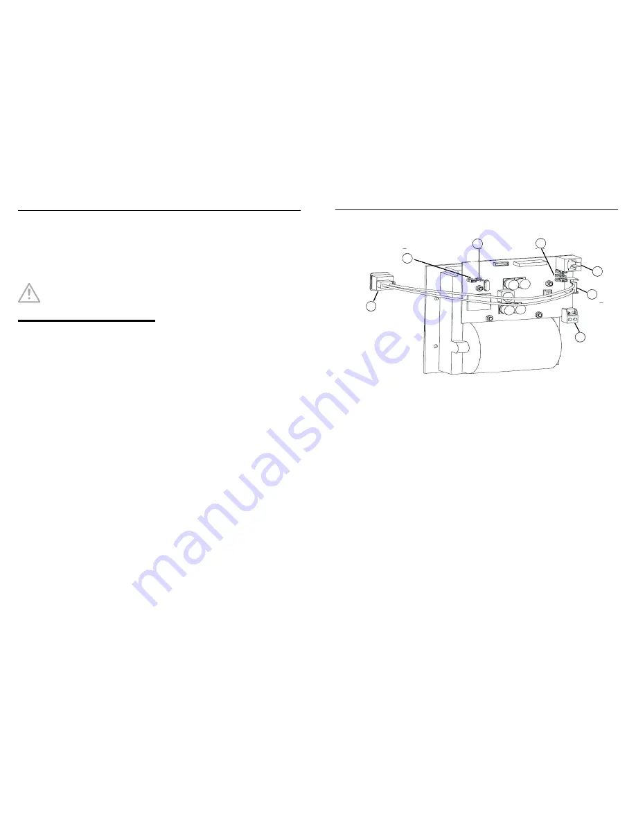
supply input TB1 (See Item 6 in
Fig. 2) of printer assembly.
Note: At TB1, c24V to the
pin VM and -0V to the pin 0V respec-
tively.
– Power and data cables may be run
together if required through an
appropriate conduit and should be
separated from other field wiring of
the MX/T2000 panel.
9 Fit the paper roll to printer mecha-
nism, as described in Paper Roll
Replacement.
10 Replace the 0.5A fuse taken from the
FB800 fuseboard.
11 Check that the jumper links are cor-
rectly fitted on the Printed Circuit
Board.
– Configure the jumper links as indi-
cated in Fig. 2.
12 Configure the printer using MZX CON-
SYS as follows:
– In the Printers dialog box:
Printer Address - COM1, tick Ena-
bled
Printer Name - PRINTER
Paper Width -Narrow (40)
Printer Type - Standard Printer
Quiescent Logging - tick if required
Default Printer - tick
– In the Communication Ports dialog
box:
Set the Baud Rate to 9600
13 Save the printer configuration, then
download the new configuration.
14 The PRN800 is now installed.
NOTICE
All necessary precautions
must be taken to protect
wiring and PCBs.
MZX Fire alarm system
PRN800 MX Printer
Fixing Instructions Doc. version 3
3/4
Fig. 2: Printer configuration - Jumper setting (1-3) and wiring connections (4-7)
1 –LK6 ON
2 –LK5 OFF
3 –LK1 RIGHT, LK2 OFF, LK4 RIGHT
4 –Printer connector for RS232
5 –Cable to paper feed button
6 –Printer header connector for power supply cable
7 –Connection to paper feed button
1
2
3
4
5
6
7


