


408-4342
PRO-CRIMPER III Hand Crimping Tool Assembly 58603-1
Rev A
4 of 5
Tyco Electronics Corporation
3. Position the contact so that the mating end of
the contact is on the locator side of the tool, and so
that the open “U” of the wire and insulation barrels
must face the top of the tool. Place the contact up
into the nest so that the movable locator drops into
the slot in the contact. Refer to Figure 3. Butt the
front end of the wire barrel against the movable
locator.
Make sure that both sides of the insulation barrel
are started evenly into the crimping section. Do
NOT attempt to crimp an improperly positioned
contact.
4. Hold the contact in position and squeeze the
tool handles together until ratchet engages
sufficiently to hold the contact in position. Do NOT
deform insulation barrel or wire barrel.
5. Insert stripped wire into contact insulation and
wire barrels until it is butted against the wire stop,
as shown in Figure 3.
6. Holding the wire in place, squeeze tool handles
together until ratchet releases. Allow tool handles
to open and remove crimped contact.
The crimped contact may stick in the crimping
area, but the contact can be easily removed by
pushing downward on the top of the locator (see
Figure 3).
7. Check the contact crimp height as described in
Section 6, CRIMP HEIGHT INSPECTION. If
necessary, adjust the crimp height as described in
Section 7, CRIMP HEIGHT ADJUSTMENT.
6. CRIMP HEIGHT INSPECTION
This inspection requires the use of a micrometer with
a modified anvil.
Tyco Electronics does not manufacture or market
these micrometers. However TE recommends the
modified micrometer (Crimp Height Comparator
RS-1019-5LP) or the digital micrometer from
Mitutoyo.
Proceed as follows:
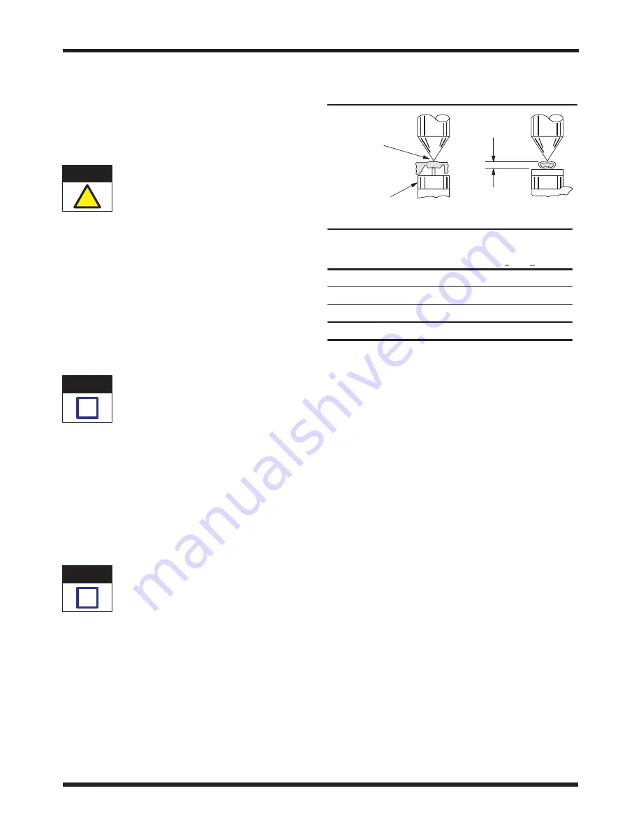
1. Refer to Figure 4 and select a wire (maximum
size) for each crimp section listed.
2. Refer to Section 5, CRIMPING PROCEDURE,
and crimp the contact(s) accordingly.
3. Using a crimp height comparator, measure the
wire barrel crimp height as shown in Figure 4. If the
crimp height conforms to that shown in the table,
the tool is considered dimensionally correct. If not,
the tool must be adjusted. Refer to Section 7,
CRIMP HEIGHT ADJUSTMENT.
Position Point
on Center of
Wire Barrel
Opposite
Seam
A"
Modified Anvil
WIRE SIZE
CRIMP SECTION
CRIMP HEIGHT
DIMENSION A
mm
2
(Max)
(Color Marking)
DIMENSION A
(+0.05 [+.002])
2.5
Yellow
1.88 [.0740]
1.5
Blue
1.58 [.0621]
1.0
Red
1.36 [.0535]
0.75
Green
1.27 [.0500]
Figure 4
7. RATCHET (Crimp Height) ADJUSTMENT
(Figure 5)
1. Remove the lockscrew from the ratchet
adjustment wheel.
2. With a screwdriver, adjust the ratchet wheel
from the locator side of the tool.
3. Observe the ratchet adjustment wheel. If a
tighter crimp is required, rotate the adjustment
wheel
counterclockwise to a higher–numbered
setting. If a looser crimp is required, rotate the
adjustment wheel
clockwise to a lower–numbered
setting.
4. Re–assemble the lockscrew.
5. Make a sample crimp and measure the crimp
height. If the dimension is acceptable, replace and
secure the lockscrew. If the dimension is
unacceptable, continue to adjust the ratchet, and
again measure a sample crimp.
8. MAINTENANCE
Ensure that the tool and dies are clean by wiping
them with a clean, soft cloth. Remove any debris with
a clean, soft brush. Do not use objects that could
damage the tool. When not in use, keep handles
closed to prevent objects from becoming lodged in
the crimping dies, and store in a clean, dry area.
CAUTION
!
NOTE
i
NOTE
i


