


408-1537
HandTool Assembly 59282
Rev B
2 of 4
Tyco Electronics Corporation
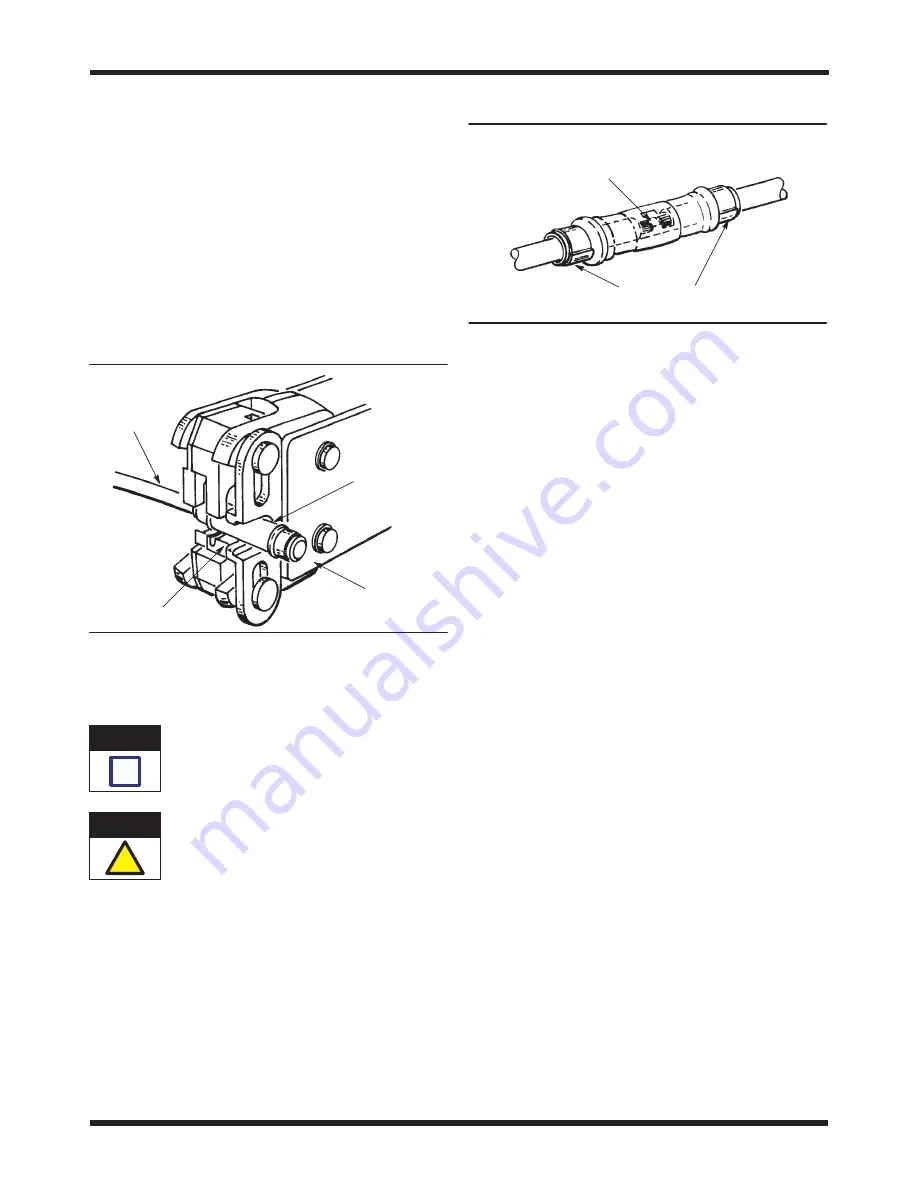
3. Insert the splice into the crimping chamber until
it butts against the locator with one end resting on
the anvils as shown in Figure 3.
4. Close the tool handles just until the splice is held
in place. DO NOT deform the splice.
5. Insert one of the stripped wires into the end of
the splice protruding from the front of the tool until
it bottoms against the wire stop.
6. Hold the wire in place, and close the tool
handles until ratchet releases.
7. Rotate the splice, and position it so that the
uncrimped end rests on the anvils. Repeat Steps 4
through 6.
Figure 3
Splice Against
Locator
Anvils
End of Wire
Against Splice
Wire Stop
Back of
Tool
8. Visually inspect the crimped splice according to
Figure 4.
A split ring indicates that the wrong wire size was
used or that a die is damaged.
The splices are not repairable. Discard and
replace any defective or damaged splice. DO
NOT re-use a terminated splice by removing the
wire.
4. MAINTENANCE AND INSPECTION
4.1. Daily Maintenance
1. Clean foreign particles from tool using a soft,
clean, lint–free cloth or brush.
2. Make sure all pins and retaining rings are
secured in their proper places. Lubricate all pins,
pivot points, and bearing surfaces with a thin coat
of any good SAE 20 motor oil. DO NOT oil
excessively.
3. Store tool in a clean, dry area with handles
closed.
Figure 4
Seam of Rings Extrude
Slightly But Are Not Split
Each Wire End (Viewed Through Window Indent)
Against Wire Stopor Flush With, or Extends
Slightly Beyond, Each Splice Wire Barrel
4.2. Periodic Inspection
Regularly scheduled inspections should be conducted
and recorded by quality control personnel. It is
recommended that the inspection procedures be
performed once a month; more often if your work
environment, company standards, or amount of tool
use indicates the need.
A. Visual Inspection
Remove all lubrication and accumulated film by
immersing the tool in a commercial degreaser that will
not damage paint or plastic. Then:
1. Check for missing or defective pins or retaining
rings. Replace parts as necessary.
2. Close handles until ratchet releases. With
handles fully open, carefully inspect the ratchet
assembly, tool head, and die surfaces.
Worn, cracked, pitted, or chipped die surfaces, or
other obvious wear or damage to the ratchet or tool
head requires removal of the tool from service. Refer
to Section 5, REPLACEMENT AND REPAIR.
B. Gaging the Crimping Chamber
This inspection requires the use of plug gages
conforming to the dimensions provided in Figure 5.
Gage each crimping chamber section separately as
follows:
1. Remove traces of oil or dirt from the crimping
chamber and plug gage.
2. If gaging the insulation barrel section of the
crimping chamber, insert a 0.13 mm [.005 in.] shim
between the bottoming surfaces of the dies.
3. Close the tool handles until the dies are
bottomed and hold them in this position. Do not
force the dies beyond initial contact.
4. Align the plug gage GO element with the
crimping chamber section. Push the element
NOTE
i
CAUTION
!


