


408-1559
Hand Crimping Tools
5 of 10
Rev P
Tyco Electronics Corporation
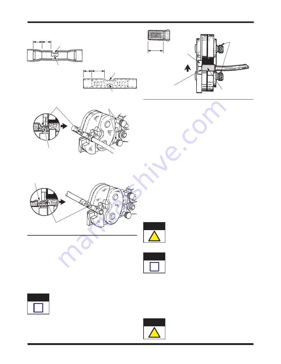
Figure 5
Butt Splices
C" B"
PIDG Splice
B" Equals Wire Barrel
C" Equals Insulation Barrel
C"
B"
PLASTI-GRIP Splice
Window Indent
Wire Stop
Wire Stop
Window
Indent
Locator Seats in
Window Indent
of Splice
First
Crimp
End of Wire Conductor Butts
Against Splice Wire Stop
Insulation CrimpAdjustment
Pins in No. 3 Position
Second
Crimp
Locator Seats in Window
Indent of Splice
End of Wire Conductor Butts
Against Splice Wire Stop
4. CRIMP INSPECTION
Inspect crimped terminals and splices by checking the
features described in Figure 7. Terminals and splices
not meeting these conditions should NOT be used.
5. INSULATION CRIMP ADJUSTMENTS
5.1. For PIDG Terminals and Splices
PIDG terminalsand splicesfeature a wire
insulation grip."
The insulation crimping section of the hand tool has
three positions: 1 (tight), 2 (medium), and 3 (loose).
To adjust the section:
Figure 6
Spare Wire Caps
Wire Barrel
Locator
Insulation
Adjustment
Pins in No. 3
Position
Wire Bottoms
in Cap
Raise Locator so
that End of Cap
Rests Against
Recessed Surface
of Locator
1. Insert the insulation crimp adjustment pins into
the No. 3 position. Refer to Figure 1 or Figure 5.
2. Place the terminal or splice into the crimping
jaws as shown in Figure 4 or Figure 5.
3. Insert the UNSTRIPPED wire into ONLY the
insulation barrel (refer to Figure 4 or Figure 5)
portion of the terminal or splice.
4. Close the tool handles to complete the crimp.
5. Remove the crimped terminal or splice and
check the insulation crimp by bending the wire
back and forth once. The terminal or splice should
retain its grip on the wire insulation. If the wire pulls
out, set the insulation crimp adjustment pins to the
next higher position (No. 2).
6. Perform another crimp and repeat the
adjustment as necessary until the correct insulation
grip is attained. Do not use a tighter setting than
required.
Make sure that both insulation crimp adjustment
pins are in the same position.
5.2. For PLASTI-GRIP Terminals and Splices
PLASTI-GRIP terminalsand splicesfeature a
wire insulation support" only. The terminal or
splice insulation should ideally be in contact with
the wire insulation.
1. Set adjustment pins in position No. 3 for wire
having a large insulation diameter.
2. Set adjustment pins in position No. 2 for wire
having a medium insulation diameter.
3. Set adjustment pins in position No. 1 for wire
having a small insulation diameter.
Make sure that both insulation crimp adjustment
pins are in the same position.
NOTE
i
CAUTION
!
NOTE
i
CAUTION
!


