background image

http://www.tyan.com

20

Chapter 2

Board Installation

4. Installing the CPU and Cooling Fan

Socket 7 processors (see Specifications
on page 5) can be used on the Trinity
ATX. Please refer to page 14 for the cor-
rect CPU jumper settings for your CPU.
Remember:

The CPU is a sensitive electronic
component and it can easily be
damaged by static electricity. Do
not touch the CPU pins with your
fingers.

Before the CPU is installed, the

mainboard must be placed on a flat
surface. You should be able to insert
the CPU with minimal, but firm,
pressure. Do not press down hard on the
CPU.

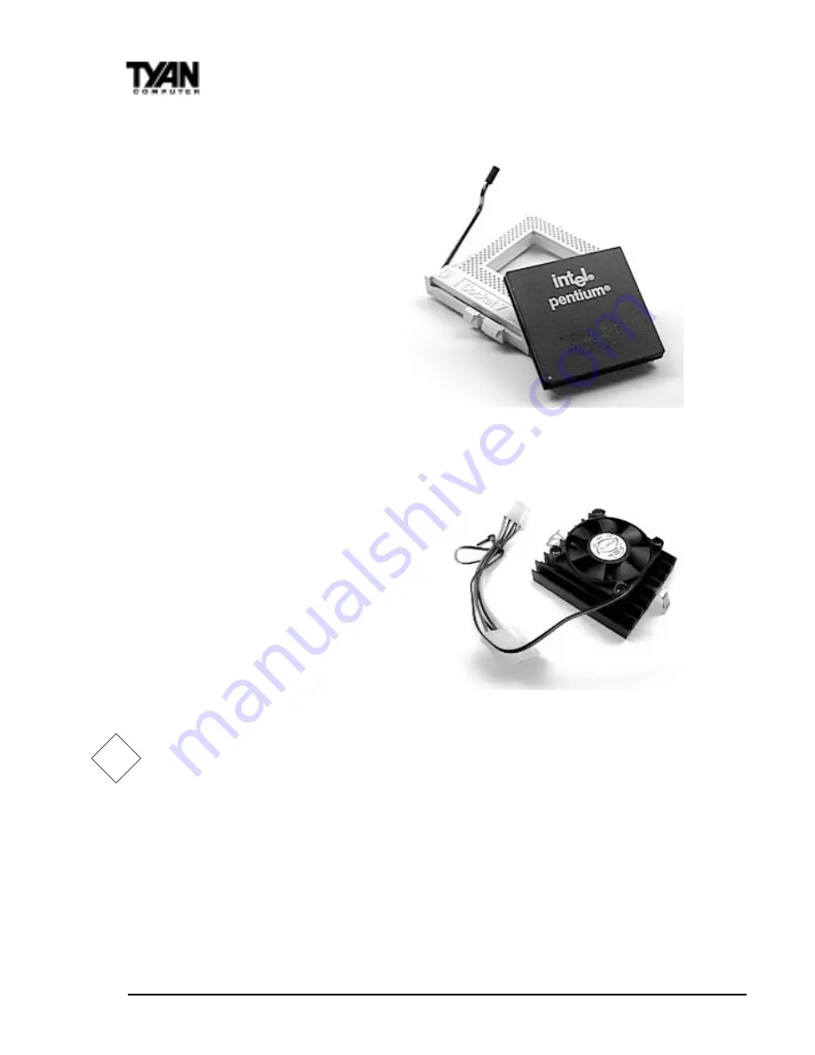
In Figure 2-6, you can see the CPU and the
ZIF socket. Notice that the arm of the ZIF
socket is up. When this arm is up, the CPU
is unlocked from the socket and allows
you to remove or install a CPU. As the ZIF
socket is keyed to the processor that you
are using, you will only be able to install
the CPU one way, thus eliminating the
chance for error. Pin 1 on the CPU is
denoted by a small dot on one of the corners and Pin 1 on the ZIF socket is
denoted by an angled corner. Never force a CPU into a socket. Forcing a CPU
to seat will bend the pins on the CPU and possibly damage the motherboard.
Check with your vendor or manufacturer for proper voltage selection.

Push down lightly on the CPU, and lower the arm on the ZIF socket to secure
the CPU. A squeaking noise is normal as the arm lowers. After the CPU is
securely seated, install the appropriate cooling device (Figure 2-7). Tyan
strongly recomends a heatsink/fan combination. Consult with your case
manufacturer for other cooling options.

!!!!!

important!

Figure 2-7

Figure 2-6

Summary of Contents for TRINITY ATX

Page 1: ...re Inc Windows is a trademark of Microsoft Corporation IBM PC AT PS 2 are trademarks of IBM Corporation INTEL Pentium Pentium MMX are trademarks of Intel Corporation S1598 Trinity ATX is a trademark o...

Page 2: ...Motherboard in the Chassis 16 InstallingMemory 17 Installing CPU and Cooling Fan 20 Connecting IDE and Floppy Drives 22 Connecting the Power Supply 23 Installing Add on Cards 24 Connecting PS 2 USB Se...

Page 3: ...This page has been intentionally left blank...

Page 4: ...s high performance capabilities that are ideal for a wide range of demanding applications such as CAD CAM CAE desktop publishing 3D animation and video production This system board achieves high relia...

Page 5: ...r system which are indicated by this icon However it is in your best interest to read an entire section and perhaps the entire manual before you begin to fiddle with your motherboard While we have ale...

Page 6: ...unbuffered 168 pin DIMM sockets Maximum rated memory bus speed 100MHz Supports EDO SDRAM Parity and ECC ECC only with Parity memory ExpansionSlots One AGP Slot supports 66 133MHz speeds Five 32 bit PC...

Page 7: ...ATX 2 01 power supply Software Specifications OS Operates with Windows 95 Windows 98 Windows NT4 0 OS 2 v4 0 Novell Netware v5 0 andSCOUnixv5 05 Technical Support If a problem arises with your system...

Page 8: ...roduct problems This warranty only covers normal customer use and does not cover damages incurred during shipping or failure due to the alteration misuse abuse or improper maintenance of products For...

Page 9: ...verCD Precautions What s the first thing I should do The first thing you should do is read this user s manual It contains important information which will make configuration and setup much easier Here...

Page 10: ...operly seated the board should still be on an antistatic mat Do not touch the bottom of the board Remember don t take any electronic device out of its protective bag until you are ready to actually in...

Page 11: ...ted by slipping the blue plastic jumper connector overtop of two adjacent jumper pins indicated by 1 2 or 2 3 The metal rod inside the plastic shell bridges the gap between the two pins completing the...

Page 12: ...olt lithium battery VIA MVP3 chipset VIA MVP3 chipset ISA slot 2 ISA slot 1 PCI slot 5 Secondary IDE connector Primary IDE connector Floppy drive connector DIMM bank 2 DIMM bank 3 DIMM bank 1 ATX powe...

Page 13: ...X 13 INSTALL Picture of Motherboard Features 3 DIMM slots Award BIOS AGP port 2 ISA slots 5 PCI slots VIA MVP3 ZIF Socket 7 PS 2 mouse ATX power connector PS 2 Keyboard CPU temperature sensor 1MB L2 c...

Page 14: ...N O N O x 5 F F O N O N O x 5 5 F F O F F O N O important 1 A CPU Bus Speed Settings 1 B CPU Clock Multiplier 1 C CPU Core Voltage Settings e g a t l o V U P C 8 P J 9 P J 0 1 P J 1 1 P J 2 1 P J V 3...

Page 15: ...s then return jumper JP13 to pins 1 and 2 4 Power on the system again By following this procedure you will erase your password and reset the CMOS to the BIOS defaults 1 D J3 External Pin Assignments S...

Page 16: ...tem If the external battery for the RTC is low you will lose your BIOS settings Normally the life span of an external battery is 2 years If yours is running low you will need to replace it with a new...

Page 17: ...for high performance If you buy a TYAN board you are getting the best system available To make installation easy and trouble free get high quality parts Some brands we recommend are Corsair Microsyst...

Page 18: ...onto the notches in the ends of the DIMM see Figure 2 4 on the next page To remove your DIMM simply pull the clips back and pull up on the module Place the DIMMs in an anti static bag as soon as you...

Page 19: ...memory installation The mainboard supports 32MB 64MB 128MB SDRAM modules PC 100 DIMMs are required if CPU bus speed is at 100MHz SDRAM Parity and ECC using Parity memory memory is supported CacheMemor...

Page 20: ...is unlocked from the socket and allows you to remove or install a CPU As the ZIF socket is keyed to the processor that you are using you will only be able to install the CPU one way thus eliminating...

Page 21: ...1 on the motherboard Plug the CPU s cooling fan cable into the cooling fan connector on the board There will be a plastic clip assembly similar to that of theATX power connector that will force you to...

Page 22: ...urer or documentation for more information ATA 66 IDE hard drives require a special IDE cable which has additional grounding wires The cable is sold separately and is required when using ATA 66 drives...

Page 23: ...ime Some symptoms of incorrectly installed floppies are Floppy drives are not detected usually caused by faulty cables backward cables or a bad floppy or motherboard Try another single floppy drive to...

Page 24: ...ling Add on Cards There are a few rules you need to follow when plugging in a card In order to assure proper operation and a quick installation adhere to these guidelines If you are going to install a...

Page 25: ...problems have a qualified professional install your cards for you or contact your card manufacturer Remember always read the manuals and installation notes that come with the adapter cards They conta...

Page 26: ...have had a fairly uneventful time installing our products If you did encounter problems your dealer will be able to help you or you can consult one of our many technical support resources see page 7...

Page 27: ...Q How do I identify Pin 1 of a 3 pin jumper A There should be a small numeral 1 silkscreened on the board in white next to pin 1 You can also look on the back side of the board pin 1 is identified wit...

Page 28: ...r USB in PNP PCP Configuration Setup menu NOTE II this driver is for Win95 users only however some Win98 users may need to install this driver who are having conflicts in Device Manager There are no d...

Page 29: ...S1598 TrinityATX 29 INSTALL This page intentionally left blank...

Page 30: ...M PC AT compatible personal computers It supports Intel x86 and compatible processors The BIOS provides critical low level support for the system central processing memory and I O subsystems The Elite...

Page 31: ...you still wish to enter Setup restart the system to try again by turning it OFF then ON or pressing the RESET button on the system case You may also restart by simultaneously pressing Ctrl Alt and De...

Page 32: ...M o t n r u t e r d n a e g a p t n e r r u c y e k p U g P s e g n a h c e k a m r o e u l a v c i r e m u n e h t e s a e r c n I y e k n D g P s e g n a h c e k a m r o e u l a v c i r e m u n e h...

Page 33: ...ty a Main Menu similar to the one shown below appears on the screen The Main Menu allows you to select from several Setup functions and two exit choices Use the arrow keys to select among the items an...

Page 34: ...oller in your system Supervisor User Password Change set or disable a password In BIOS versions that allow separate user and supervisor passwords only the supervisor password permits access to Setup T...

Page 35: ...ired field Press the PgUp or PgDn key to increment the setting or type the desired value into the field HARDDISKS The BIOS supports up to four IDE drives This section does not show information about o...

Page 36: ...Each defined drive type has a specified number of cylinders number of heads write precompensation factor landing zone and number of sectors Drives whose specifications do not accommodate any pre defi...

Page 37: ...i r d d e d i s e l b u o d h c n i 2 1 3 n i 5 3 M 8 8 2 y t i c a p a c e t y b a g e m 8 8 2 e v i r d d e d i s e l b u o d h c n i 2 1 3 A G V A G E A G V A G E r o F y a r r A s c i h p a r G o...

Page 38: ...DOS operating system and conventional applications use this area Extended Memory Above the 1 MB boundary Early IBM personal computers could not use memory above 1 MB but current PCs and their software...

Page 39: ...PCI VGA Palette Snoop Disabled OS Select For DRAM 64MB Non OS2 ESC Quit Select Item F1 Help PU PD Modify F5 Old Values Shift F2 Color F6 Load BIOS Defaults F7 Load Setup Defaults BIOS Setting Option B...

Page 40: ...DRAM into cache memory for even faster access by the CPU The External Cache field may not appear if your system does not have external cache memory Quick Power On Self Test Select Enabled to reduce th...

Page 41: ...tem chipset controls Gate A20 When set to Normal a pin in the keyboard controller controls Gate A20 Setting Gate A20 to Fast improves system speed particularly with OS 2 and Windows MemoryParity ECCCh...

Page 42: ...nto system RAM where the CPU can read it through the 16 bit or 32 bit DRAM bus Firmware not shadowed must be read by the system through the 8 bit X bus Shadowing improves the performance of the system...

Page 43: ...Current CPU Temperature 35C 95F Bank 2 3 DRAM Timing FP EDO 70ns Current System Temp 27C 80F Bank 4 5 DRAM Timing FP EDO 70ns Current CPUFAN Speed 0RPM SDRAM Cycle Length 2 Current SYSFAN Speed 0RPM...

Page 44: ...m the CPU Pipelining improves system performance Setting Option BIOS Default Setup Default Bank 0 1 DRAMTiming SDRAM10ns SDRAM10ns Bank 2 3 DRAMTiming FP EDO 70ns FP EDO 70ns Bank 4 5 DRAMTiming FP ED...

Page 45: ...r ROM When this area is reserved it cannot be cached The user information of peripherals that need to use this area of system memory usually discusses their memory requirements AGPAperture Size Select...

Page 46: ...ode Disabled IRQ11 Reserved Secondary Suspend Mode Disabled IRQ12 PS 2 Mouse Primary PM Events IRQ13 Coprocessor Disabled VGA OFF IRQ14 Hard Disk Primary LPT COM LPT COM IRQ15 Reserved Disabled HDD FD...

Page 47: ...U M P e h t n i s d o i r e p t u o e m i t t c e l e S y l l a u d i v i d n i e d o m h c a e t e S g n i w o l l o f n o i t c e s s r e m i T g n i v a S n i M h c a e n i r u o h 1 s i d o i r e...

Page 48: ...ode HDDPowerDown After the selected period of drive inactivity 1 to 15 minutes the hard disk drive powers down while all other devices remain active H V k n a l B C N Y S s t r o p n o i t a z i n o r...

Page 49: ...ctivity is a PM event HDD FDD When On any hard drive or floppy drive activity is a PM event DMA master When On any DMA or bus master activity is a PM event ModemRingResume When Enabled an input signal...

Page 50: ...h T y r a d n o c e S s i t s e u q e r t p u r r e t n i e h t t u b p u e k a w t o n s e o d m e t s y s e h T y l l a c i p y t e r a s t p u r r e t n i y r a d n o c e S d e s s e c o r p e l i...

Page 51: ...lp PU PD Modify F5 Old Values Shift F2 Color F6 Load BIOS Defaults F7 Load Setup Defaults CPU to PCI Write Buffer Enabled PCI Dynamic Bursting Disabled PCI Master 0 WS Write Enabled PCI Delay Transact...

Page 52: ...ystem reconfiguration has caused such a serious conflict that the operating system cannot boot Setting Option BIOS Default Setup Default DMA 1 assigned to PCI ISA PnP PCI ISA PnP DMA 3 assigned to PCI...

Page 53: ...s compliant with the Plug and Play standard whether designed for PCI or ISA bus architecture CPU to PCI Write Buffer When this field is Enabled writes from the CPU to the PCI bus are buffered to compe...

Page 54: ...t or modify some fields OnChip IDE First Channel Enabled Onboard Parallel Port 378 IRQ7 OnChip IDE Second Channel Enabled IDE Prefetch Mode Disabled IDE HDD Block Mode Disabled IDE Primary Master PIO...

Page 55: ...etection of the optimal number of block read writes per sector that the drive can support IDEPrimary SecondaryMaster SlavePIO The four IDE PIO Programmed Input Output fields let you set a PIO mode 0 4...

Page 56: ...terface supports the system automatically determines the optimal data transfer rate for each IDE device Init Display First Select the type of display adapter used in your system OnboardFDDController S...

Page 57: ...d Flash Writer Utility You can upgrade the BIOS on your motherboard by using the Flash Memory Writer FMW utility This utility can be downloaded from TYAN s BBS and from the TYAN website The system BIO...

Page 58: ...un FMW from a backup copy of your support disk You can make your back up floppy bootable when you format it and use one disk for both purposes 2 If you are using MS DOS 6 x you can use the feature tha...

Page 59: ...y diskette before you program the new BIOS This leaves you with a backup of your original BIOS in case you need to re install it If you cannot successfully program the new BIOS file for some reason re...

Page 60: ...mpt to press F1 to continue or press DEL to enter Setup Beep Currently the only beep code indicates that a video error has occurred and the BIOS cannot initialize the video screen to display any addit...

Page 61: ...itialize the floppy drive controller or the drive Make sure the controller is installed correctly If no floppy drives are installed be sure the Diskette Drive selection in Setup is set to NONE or AUTO...

Page 62: ...stable minimal performance system operations Press TAB to show POST screen System OEMs may replace the EliteBIOS POST display with their own propri etary display Including this message in the OEM dis...

Page 63: ...S1598 TrinityATX 63 SYSTEM This page has been intentionally left blank...

Page 64: ...transmission during both the rising and falling ends of the clock cycle yielding an effective speed of 133MHz The AT was the original form factor of IBM s PC ATAPI ATAttachment Packet Interface also...

Page 65: ...sh Informa tion stored in a buffer is temporarily stored not permanently saved A bus is a data pathway The term is used especially to refer to the connection between the processor and system memory an...

Page 66: ...nnels are similar to IRQs DMAchannels allow hardware devices like sound cards or keyboards to access the main memory without involving the CPU This frees up CPU resources for other tasks As with IRQs...

Page 67: ...the horizontal properties of the monitor IC Integrated Circuit is the formal name for the computer chip IDE Integrated Device or Drive Electronics is a simple self contained hard drive interface It ca...

Page 68: ...em as opposed to a network bus which connects multiple systems The PCI PIO PCI Programmable Input Output modes are the data transfer modes used by IDE drives These modes use the CPU for data transfer...

Page 69: ...c RAM is so called because it can keep two sets of memory addresses open simultaneously By transferring data alter nately from one set of addresses and then the other SDRAM cuts down on the delays ass...

Page 70: ...mouse keyboard or joystick port It is fast enough to support video transfer and is capable of supporting up to 127 daisy chained peripheral devices VGA Video Graphics Array is the PC video display st...

Page 71: ...nt and receiver Plug the equipment into an outlet on a circuit different from that of the receiver Consult the dealer or an experienced radio television technician for help CAUTION LITHIUMBATTERIESinc...

Page 72: ...8 P J 9 P J 0 1 P J 1 1 P J 2 1 P J V 3 1 F F O F F O F F O F F O N O V 4 1 F F O N O F F O F F O N O V 5 1 F F O F F O N O F F O N O V 6 1 F F O N O N O F F O N O V 7 1 F F O F F O F F O N O N O V 8...

Reviews: