TYAN B5191 Service Engineer'S Manual Download Page 29

Chapter 2: Setting Up

21

Rackmounting the Server

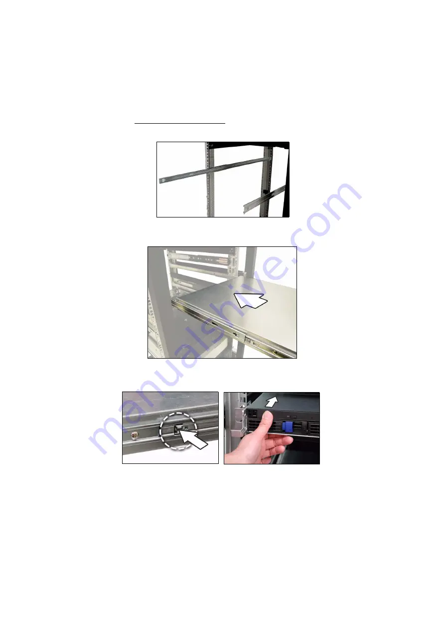
8. Draw out the middle rail to the latch position.

9. Lift the chassis and then insert the inner slide rails into 

the middle rails.

10. Push the chassis in and press the latch key (A). Then 

push the whole system into the rack (B).

A

B

Summary of Contents for B5191

Page 1: ...Tank GT20 B5191 Service Engineer s Manual...

Page 2: ......

Page 3: ...AN retains the right to make changes to product descriptions and or specifications at any time without notice In no event will TYAN be held liable for any direct or indirect incidental or consequentia...

Page 4: ...ent into an outlet on a circuit different from that of the receiver Consult the dealer on an experienced radio television technician for help Notice for Canada This apparatus complies with the Class B...

Page 5: ...nd provides block diagrams of the system Chapter 2 Covers procedures on installing the CPU mem ory module PCI card and hard drive Chapter 3 Covers removal and replacement procedures for pre installed...

Page 6: ...is pin If your outlet does not support this kind of plug contact your electrician to replace your obsolete outlet Do not place anything on the power cord Place the power cord where it will not be in t...

Page 7: ...17 2 1 1 Installing the Server in a Rack 17 2 2 Installing Motherboard Components 23 2 2 1 Removing the Chassis Cover 23 2 2 2 Installing the CPU Heatsink and Air Duct 24 2 2 3 Installing the Memory...

Page 8: ...ter Board Connector Pin Definition 44 3 7 Replacing the SATA Backplane 49 3 7 1 S ATA Backplane M1208 Features 50 3 8 Replacing the Cooling Fan 52 3 9 Replacing the Power Supply 53 Appendix I BIOS Dif...

Page 9: ...a lightning fast PCI Express bus implementation The TankTM GT20 B5191 not only empowers your company in today s demanding IT environment but also offers a smooth path for future application usage TYA...

Page 10: ...ts 3 LAN ports Front Panel Features I O 2 USB 2 0 ports LED indicators HDD active LEDs 2 LAN LEDs 1 Power LED 1 System warn ing LED ID LED Switches Power Reset NMI ID Integrated Storage Controller ICH...

Page 11: ...Sunon 40 40 28mm 14500rpm heavy duty fans 1 passive CPU heatsink Regulatory FCC Class B Declaration of Con formity CE Declaration of Conformity Environment Temperature Operating temperature 5oC 35oC...

Page 12: ...Box Open the box carefully and ensure that all components are present and undamaged The product should arrive pack aged as illustrated below Contact your distributor if anything is missing or appears...

Page 13: ...s are missing or appear damaged contact your retailer or browse to Tyan s Web site for service 1 x Tyan driver CD Power Cords Left to right Europe US HDD Screws Mounting Ears Screws Heatsink x 1 Bareb...

Page 14: ...Chapter 1 Overview Rail Kit Mounting Bracket x 4 Screws Kit Front Rear Sliding Brackets Front L Bracket x 2 Rear L Bracket x 2 Sliding Rails x 2 FDD Cable FDD Rails Screws FDD Kit FDD Backplane Cable...

Page 15: ...4 2 Rear View CD ROM Drive Hard Drive Bay x 4 HDD Activity LED Power Switch Reset Switch USB Ports Warning LED 2x LAN LEDs ID Switch NMI Switch ID LED Power LED Power Supply Socket PS 2 Mouse Keyboar...

Page 16: ...LAN linked LAN accessing No LAN linked Warning Red OFF ON OFF Fan fails Normal ID LED Blue OFF ON OFF System is identified System is not identified Hot Swappable HDD Tray Power LED Green OFF ON OFF P...

Page 17: ...N OFF Gigabit mode 100M mode 10M mode RJ45 NIC2 Linkage Left Side Green Green OFF ON Blinking OFF LAN linked LAN accessing No LAN linked RJ45 NIC2 Mode Right Side Amber Green OFF ON ON OFF Gigabit mod...

Page 18: ...PCI X Slot 2 Link Bar 3 Memory Slots 4 EPS 12V Power Supply 5 CPU Socket 6 System Fans Left to right FAN5 FAN4 FAN3 FAN2 FAN1 7 Adapter Board 8 SATA Backplane 9 LED Control Board Cable 10 Four SATA H...

Page 19: ...Chapter 1 Overview 11 1 4 5 Motherboard S5191 Block Diagram...

Page 20: ...P1 PCIX E1 PCIX E1 J11 CPU P 2 W PW1 J9 1 LAN2 LAN1 VGA COM1 LAN3 USBx2 K B M S JP3 1 1 FDD COM2 LPT SMDC IDE 1 JP3 1 JP1 JP2 1 JP6 1 BIOS J 7 P JP9 1 1 JP8 1 J12 1 1 1 J22 J21 J24 J25 J20 1 J19 1 JP...

Page 21: ...J18 Front Fan Connector J15 CPU Fan Connector J21 J22 J24 J25 Serial ATA RAID Connector JP1 JP2 SMDC ASF2 0 Select Header JP3 LAN3 Enable Disable Jumper JP6 PCI X Speed Select Header JP7 JP9 Front Pa...

Page 22: ...14 Chapter 1 Overview...

Page 23: ...ontainers to keep small components separated Putting all small components in separate containers prevents them from becoming lost Adequate lighting and proper tools can prevent you from accidentally d...

Page 24: ...any other grounded appliance Avoid touching motherboard components IC chips connectors memory modules and leads The motherboard is pre installed in the system When removing the motherboard always pla...

Page 25: ...Screws Kit x 1 Mounting Brackets x 4 2 1 1 Installing the Server in a Rack Follow these instructions to mount the Tank GT20 into an industry standard 19 rack NOTE Before mounting the Tank GT20 in a ra...

Page 26: ...sing 2 screws from the supplied screws kit 2 Draw out the inner rails from rail assembly Install inner rails to left and right sides of chassis using 2 M4 5L D screws for each side Installing Outer Ra...

Page 27: ...Chapter 2 Setting Up 19 4 Locate the front and rear brackets 5 Reserve 40mm on the front bracket Secure the front bracket to outer rail with 2 M4 4L C screws Rear Bracket x2 Front Bracket x2...

Page 28: ...tep 2 on rear bracket Secure the rear bracket to outer rail with 2 M4 4L C screws 7 Secure the outer rail to the rack using 2 brackets and 4 M4 8L E screws for each side A Secure the mounting brackets...

Page 29: ...the Server 8 Draw out the middle rail to the latch position 9 Lift the chassis and then insert the inner slide rails into the middle rails 10 Push the chassis in and press the latch key A Then push t...

Page 30: ...g Up 11 Secure the mounting ears of chassis to the rack with 2 M4 15L F screws NOTE To avoid injury it is strongly recommended that two people lift the Tank GT20 into the place while a third person sc...

Page 31: ...nstall components on to the motherboard including CPU memory modules and PCI card 2 2 1 Removing the Chassis Cover Follow these instructions to remove the Tank GT20 chassis cover 1 Release the screw o...

Page 32: ...e CPU Heatsink and Air Duct Follow these instructions to install the CPU CPU heatsink and air duct 1 Release the pre installed air duct Locate the CPU socket 2 Remove the cover on the CPU socket cap 3...

Page 33: ...4 Press and pull the lever in the direction as illustrated 5 Open the socket in the direction as illustrated 6 Place CPU on the socket ensuring that the edge with tri angle mark aims at the edge of so...

Page 34: ...ng Up 7 Close the cover and secure the CPU socket in the direc tion shown 8 Secure the heatsink with 4 screws NOTE Remember to install the washer and nut while install ing the screws 9 Secure the air...

Page 35: ...s the memory slot locking levers in the direction of the arrows as shown in the following illustration 3 Align the memory module with the slot The module has indentations that align with notches in th...

Page 36: ...Push the tab of PCI slot on the rear panel in the direction as shown to release the bracket 2 Move the bracket to right as shown and then take off the bracket A 3 Insert the PCI card in the direction...

Page 37: ...ebone system supports Serial ATA hard drives Follow these instructions to install a SATA hard drive 1 Press the locking lever latch in the direction of arrow A and then pull the locking lever open B 2...

Page 38: ...Up 4 Using 4 HDD screws to secure the HDD 5 Reinsert the drive tray into the chassis A ensuring that the drive tray is completely inserted into the chassis B 6 Pressing the locking lever to secure the...

Page 39: ...D Option 1 Locate the two FDD rails and screws from the FDD kit Secure the two rails to FDD using four screws 2 Connect the FFC cable to FDD 3 Use a screw driver to take off the door of FDD tray 4 Ins...

Page 40: ...ector on M1012 adapter board 6 Locate the FDD cable from FDD kit Connect the wrinkle side to the connector on M1012 adapter board Refer to the picture below for the correct direction 7 Connect the oth...

Page 41: ...ons Use containers to keep small components separated Putting all small components in separate containers keeps them from becoming lost Adequate lighting and proper tools can prevent you from accident...

Page 42: ...body of any other grounded appli ance Avoid touching motherboard components IC chips connectors memory modules and leads The motherboard is pre installed in the system When removing the motherboard a...

Page 43: ...The following flowchart outlines the disassembly procedure Rear Components Chassis rear cover Air duct Mainboard DIMMs CPU heatsink assembly PCI card Mainboard Power supply Front Components FAN PCBs...

Page 44: ...oving the Cover Before replacing any parts you must remove the chassis cover Follow these instructions to remove the Tank GT20 chassis cover 1 Release the screw on the back side Then slide the chas si...

Page 45: ...ard 3 4 1 Disconnecting All Motherboard Cables Before replacing the motherboard or certain components remove cables connected to the motherboard Follow these instructions to remove all motherboard cab...

Page 46: ...d Follow these instructions to remove the motherboard from the chassis when all add on components have been removed 1 Release the two screws securing the link bar 2 Remove the link bar 3 Remove the el...

Page 47: ...se instructions to remove the LED control board 1 Remove the 2 screws securing the LED control board to the chassis 2 Pull the LED control board free from the chassis and unplug the ribbon and USB cab...

Page 48: ...Chapter 3 Replacing Pre Installed Components 4 Release the LED control board from the chassis After replacement insert and secure the unit to the chassis fol lowing the reverse procedures from step 1...

Page 49: ...r board you must discon nect the four SATA cables connected to the SATA back plane After that disconnect all the cables connected to the M1012 adapter board 2 Remove the Front Panel LAN ID LED and Fan...

Page 50: ...able connected to M1012 adapter board and two power cables connected to SATA back plane 5 Remove the 6 screws securing the M1012 adapter board After that you can release the M1012 adapter board from t...

Page 51: ...Connector J2 Front Panel Connector J6 Fan Connector FDD2 Slim FDD Connector J15 LCM Connector PW2 Power Connector JP1 Fan Input Select Connector J3 LAN ID LED Connector FDD1 Standard Floppy Connector...

Page 52: ...R_SW 7 RESET 8 PWR_SW 9 VOLTAGE5 10 WLED 11 EXT_INT 12 WLED 13 V5SB 14 KEY PIN 15 ICH_SMBDAT 16 GND 17 ICH_SMBCLK 18 INTRU 1 HDLED 2 HDLED 3 RESET 4 RESET 5 PW_LED 6 PW_LED 7 WLED 8 WLED 9 ICH_SMBDAT...

Page 53: ...circuit design only It might be different from the system fan naming J4 Fan TACH PWM Connector J7 Fan TACH PWM Connector J8 PWM Connector 1 LAN1_LED 2 LAN1_LED 3 LAN2_LED 4 LAN2_LED 5 LAN3_LED 6 LAN3_...

Page 54: ...CH 3 GND 4 FAN2_TACH 5 GND 6 FAN3_TACH 7 KEY PIN 8 NC 1 GND 2 FAN1_TACH 3 GND 4 FAN2_TACH 5 GND 6 FAN3_TACH 7 GND 8 FAN4_TACH 9 GND 10 FAN5_TACH 11 GND 12 FAN6_TACH 13 GND 14 FAN7_TACH 15 GND 16 FAN8_...

Page 55: ...7 J10 Fan Connector J11 Fan Connector J9 Fan Connector 1 FAN3_12VPWM 2 FAN3_TACH 3 GND 4 GND 5 FAN4_TACH 6 FAN4_12VPWM 1 FAN5_12VPWM 2 FAN5_TACH 3 GND 4 GND 5 FAN6_TACH 6 FAN6_12VPWM 1 FAN7_12VPWM 2 F...

Page 56: ...t Connector JP2 Fan Input Select Connector 1 FAN9_12VPWM 2 FAN9_TACH 3 GND 4 GND 5 FAN10_TACH 6 FAN10_12VPWM 1 LCM_ 5V 2 LCM_SIN 3 KEY PIN 4 GND 5 LCM_ 5VSB 6 LCM_SOUT Pin1 Pin2 Close Fan PWM signal f...

Page 57: ...ng the M1012 adapter board you can easily grab the two lables to lift the SATA backplane 2 Remove the ten screws that secure the bracket to the backplane 3 Release the backplane free from the bracket...

Page 58: ...50 Chapter 3 Replacing Pre Installed Components 3 7 1 S ATA Backplane M1208 Features U4 SATA 4 Connector U3 SATA 3 Connector U2 SATA 2 Connector U1 SATA 1 Connector HDD Active LED HDD Power LED...

Page 59: ...Chapter 3 Replacing Pre Installed Components 51 PW1 Power Connector J4 SATA 4 Connector J3 SATA 3 Connector J2 SATA 2 Connector J1 SATA 1 Connector PW2 Power Connector...

Page 60: ...Fan Follow these instructions to replace the cooling fans in your system 1 Locate the fan connector on the motherboard and unplug the fan cable 2 Take the fan away from the chassis 3 Replace the fan...

Page 61: ...er 3 Replacing Pre Installed Components 53 3 9 Replacing the Power Supply 1 Remove the two screws that secure the power supply to the chassis 2 Remove the screw that secure the fan assembly to the cha...

Page 62: ...54 Chapter 3 Replacing Pre Installed Components...

Page 63: ...CPU FAN FAN1 FAN2 FAN3 FAN4 FAN5 CPU Temp Ambient Temp xxxx RPM xxxx RPM xxxx RPM xxxx RPM xxxx RPM xxxx RPM xx C xxx F xx C xxx F F1 Help Select Item Change Values F9 Setup Defaults Esc Exit Select...

Page 64: ...nput type select Disabled 4 PIN 4 PIN 4 PIN 4 PIN Auto Mode Fan Control Parameters F1 Help Select Item Change Values F9 Setup Defaults Esc Exit Select Menu Enter Select X Sub Menu F10 Previous Values...

Page 65: ...1 J21 SATA 2 SATA 2 J24 SATA 3 SATA 3 J22 SATA 4 SATA 4 J25 Table 2 System Fan to M1012 Adapter Board System Fan Connect to M1012 Fan 1 J6 Fan Connector Fan 2 J10 Fan Connector Fan 3 J11 Fan Connector...

Page 66: ...wer Supply to M1208 Backplane Power Supply Connect to M1208 P4 4 pin power cable PW1 4 pin connector P6 4 pin power cable PW2 4 pin connector Table 7 M1012 Adapter Board to Motherboard M1012 Connect t...

Page 67: ...9 Table 10 Chassis Intrusion Cable Chassis intrusion switch Motherboard JP15 Pin 16 Pin 18 Table 11 FDD Related Cable Option M1012 FDD1 connector Motherboard J5 FDD M1012 FDD2 connector Slim FDD drive...

Page 68: ...formation on installing SMDC cards You may refer to the following for installing M3289 or M3290 into HDD tray or chassis Screws List including screws for Rail A Flat 6 32 x4 x16 B B type 6 32 x4 C M4...

Page 69: ...61 Installing M3289 into HDD Tray 1 Fold up the cable 2 a Choose a HDD tray b Insert the cable into the rear of HDD tray c Pull the cable out 3 Connect the cable to M3289...

Page 70: ...crews as illustrated 5 Secure M3289 onto HDD tray as illustrated 6 Insert and secure the HDD tray NOTE For internal or dummy HDD tray secure the HDD tray with 1 or 2 screws 7 Arrange and connect the c...

Page 71: ...off of 13 5mm to the location of M2 stand off as illustrated on SMDC bracket 2 Secure M3290 in reverse to 4 M2 stand offs on bracket 3 a Choose a HDD tray NOTE Refer to the location of SMDC connector...

Page 72: ...ble to SMDC connector on mainboard Be careful not to block the air flow Installing M3290 M3291 into GT20 Chassis NOTE The products produced now may not support the pro cedures below We ll provide you...

Page 73: ...d offs Secure M3290 to mainboard with 4 screws 4 Connect the cable to M3290 Arrange and connect the cable to SMDC connector on mainboard Be careful not to block the air flow 5 Reconnect the power conn...

Page 74: ...cess resources such as in depth Linux Online Support sections with downloadable Linux drivers and comprehensive compatibility reports for chassis memory and much more With all these convenient resourc...

Page 75: ...ailure due to the alteration mis use abuse or improper maintenance of products NOTE A receipt or copy of your invoice marked with the date of purchase is required before any warranty service can be re...

Reviews: