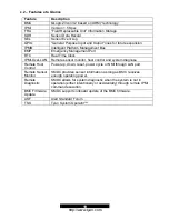
4.3 – Jumper Setting
Label
Header Type/Part
Description
Pin Layout
J1 HDR25X2_SVM_A
SVM
Edge
Connector A
Reserved
Pin 1
GND
J10 HDR2
Zircon
Firmware
Reset
Pin 2
BMC_RESET#
Pin 1
DCD
Pin 2
RXD
Pin 3
TXD
Pin 4
No Connection
Pin 5
GND
Pin 6
No Connection
Pin 7
RTS
Pin 8
CTS
Pin 9
RI
J28 HDR5X2
UART
/
Emergency
Management Port
Pin 10
No Connection
Pin 1
SDA
Pin 2
GND
Pin 3
SCL
J41
HDR4X1
BMC Private I
2
C
Pin 4
5VSB
4.4 – Specifications
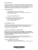
The following specifications are described below in detail.
Hardware Monitoring
Protocol and Standard
Auxiliary Communication Interface
Auxiliary SMBus / I
2
C buses
Teamed with other IPMB Devices
(PMCs and EMCs)
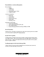
Remote Monitor, Control and Diagnostics
Sensor Repository
System Event Log
Field Replaceable Unit Information Storage
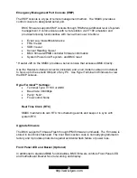
Emergency Management Port Console
Real Time Clock
Upgrade firmware
Front Panel LED and Buzzer
“Always Ready”
TYAN System Operator ™ (TSO)
OEM Drivers
20
http://www.tyan.com


