


7;5;6\VWHPV,QF
Manual 7-9547-1 12/09/14 Page 34
additional menu items include network configura-
tion, SNMP configuration, and User Administration.
When viewing these additional menu listings you
will be able to view the screen but you will not be
able to make changes without entering a pass-
word. After entering a valid password the menu
screens will switch from read-only to fully interac-
tive.
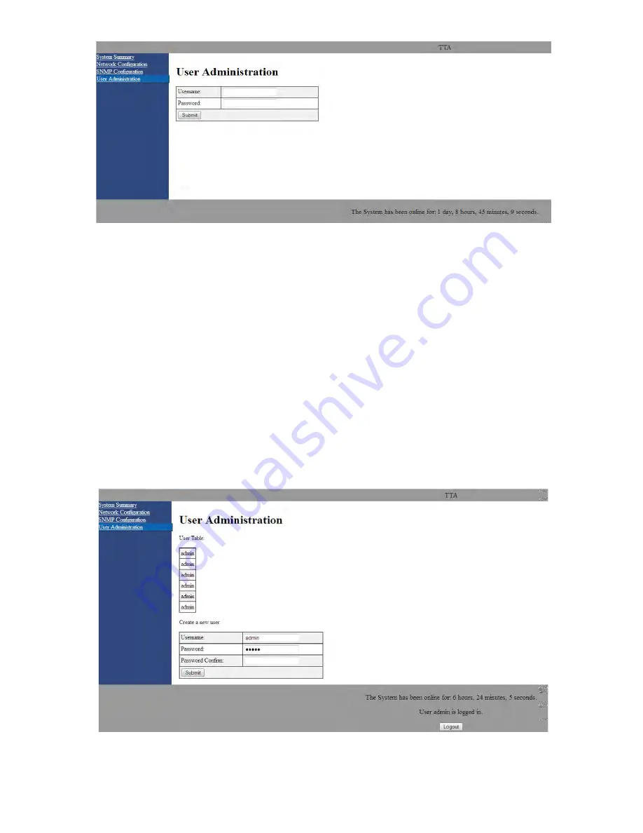
User Administration
To enter a password select the User Administration
menu listing. The User Administration menu will
appear as shown in
Figure 21
and the user will be
queried for a user name and password. The default
user name is “
admin
” and the default password is
“
admin
”. Once the correct user name and pass-
word are entered then a menu box for creating a
new user will be presented as shown in
Figure 22
.
To create a new user enter the new user name and
associated password. Confirm the new password
by entering it again then press the Submit button.
Network Configuration
The Network Configuration menu without password
access displays the status of DHCP, the current IP
address, the netmask, and the gateway as shown
in
Figure 23
. With password access the decks
MAC address is also displayed as shown in
Figure
24
. In addition, password access allows the DHCP
status, IP address, netmask, and gateway to be
Figure 21:
The User Administration menu page.
Figure 22:
Create a new user menu display.


