

- 8 -
16
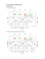
“+” Output terminal
: Positive polarity output terminal for the MASTER supply.
19
“+” Output terminal
: Positive polarity output terminal for the SLAVE supply.
17
“GND” terminal
: Earth and chassis ground.
20
“GND” terminal
: Earth and chassis ground.
18
“-” Output terminal
: Negative polarity output terminal for the MASTER supply.
21
“-” Output terminal
: Negative polarity output terminal for the SLAVE supply.
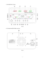
23
“+” Output terminal
: Positive polarity output terminal for 5V supply.
24
“-” Output terminal
: Negative polarity output terminal for 5V supply.
29
Output indicator
: Lights when switch is engaged (in).
30
Output ON/OFF
switch
: DC power supply output when switch is engaged (in).And when output is
off, both the voltage and current can be adjusted before the output is
resumed.
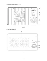
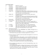
4-3. Rear Panel Control
25
Power socket
26
Fuse holder
27
AC input selector
The power transformer is designed to permit operation in 110V (115V/120V)
or 220V (230V/240V), 50/60Hz line voltage. To convert from one line voltage
to another is done by change AC input selector as shown in section 6-2.
28
Cooling fan
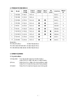
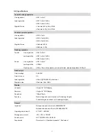
Summary of Contents for TP-2303
Page 1: ...Multi channel DC Power Supply TP Series Operation Manual V1 0 BENCHTOP INSTRUMENT ...
Page 7: ... 5 c TP 30102 60052 Front panel Fig 4 3 d TP 2303E 2305E 2303K 2305K Rear panel Fig 4 4 ...
Page 8: ... 6 e TP 2303 2305 2303TK 2305TK Rear panel Fig 4 5 f TP 30102 60052 Rear panel Fig 4 6 ...


