4
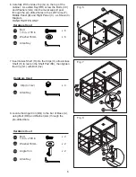
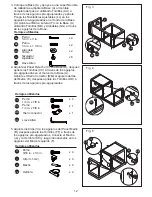
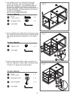
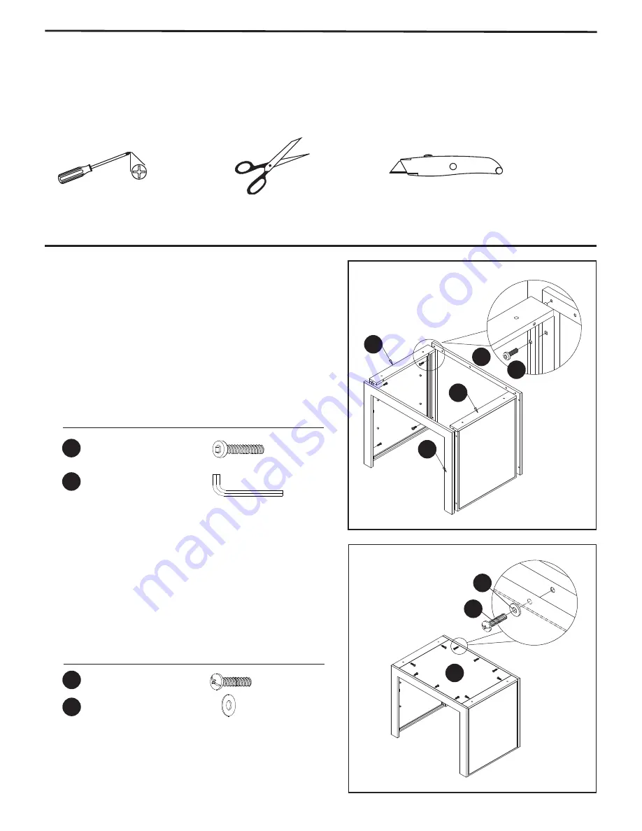
Fig. 2
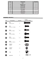
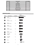
Hardware Used
EE
HH
x 10
x 10
Bolt
3/16 in. x 3/8 in.
Washer 12mm
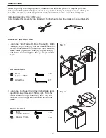
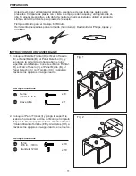
ASSEMBLY INSTRUCTIONS
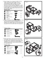
Fig. 1
B
D
Hardware Used
CC
RR
x 8
x 1
CC
EE
HH
I
E
C
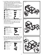
1. Locate the Front Frame (D), Back Frame (E), Middle
Panel (B), Right Panel(C), and set out face down on
a scratch-free surface. Connect the Front Frame (D),
Back Frame (E), Middle Panel (B), Right Panel(C)
with Screw (CC) and tighten through the pre-drilled
holes.
2. Locate the Top Panel (I) and lay
fi
nished side up on
top of Completed Assembly from step1. From the
inside, attach the Top Panel using Bolts (EE) and
Washers (HH) through the pre-drilled holes in the
frame.
Bolt
1/4 in. x 7/8 in.
Allen Key
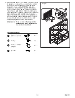
PREPARATION
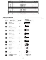
Before beginning assembly of product, make sure all parts are present. Compare parts with
package contents list and diagram above. If any part is missing or damaged, do not attempt to
assemble, install or operate the product. Contact customer service for replacement parts.
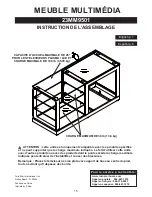
Estimated Assembly Time: 60 Minutes
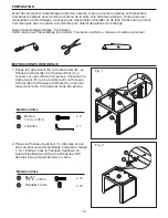
Tools Required for Assembly (not included): Phillips head screwdriver, scissors and utility knife


