background image

5

NOTE

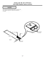
Figure 6

Ground Fault Circuit Interrupters (GFCI) are prone to nui-

sance tripping which will cause the appliance to shut down. 

GFCI’s are generally not used on circuits with power equip-

ment that must run unattended for long periods of time, un-

less required to meet local building codes and ordinances.

Electrical Connection

A grounded 115 volt, 15 amp dedicated circuit is required.

This product is factory equipped with a power supply 

cord that has a three-pronged, grounded plug. It must be 

plugged into a mating grounding type receptacle in accor-

dance with the National Electrical Code and applicable lo-

cal codes and ordinances (see Figure 6). If the circuit does 

not have a grounding type receptacle, it is the responsibility 

and obligation of the customer to provide the proper power 

supply. The third ground prong should not, under any cir-

cumstances, be cut or removed. 

INSTALLING YOUR APPLIANCE

Front grille screw

Front grille

Figure 5

Figure 3

Figure 4

Do not remove

ground prong

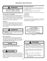
Electrical Shock Hazard

•  Do not use an extension cord with this appliance. 

They can be hazardous and can degrade product 

performance.

•  This appliance should not, under any circumstanc-

es, be installed to an un-grounded electrical supply.

•  Do not remove the grounding prong from the power 

cord. (See Figure 3).

•  Do not use an adapter. (See Figure 4).

•  Do not splash or spray water from a hose on the 

appliance. Doing so may cause an electrical shock, 

which may result in severe injury or death.

!

WARNING

Summary of Contents for TEBK24-F

Page 1: ...Twin Eagles 18912A 01 17 Model TEBK24 F TEBK242 F Outdoor Beer Dispenser ...

Page 2: ...Stainless steel maintenance 22 Energy saving tips 23 Troubleshooting 24 Obtaining service 24 Warranty 25 Important Safety Instructions Warnings and safety instructions appearing in this guide are not meant to cover all possible conditions and situa tions that may occur Common sense caution and care must be exercised when installing maintaining or operat ing this appliance Recognize Safety Symbols ...

Page 3: ...horoughly inspected before leaving our plant Responsibility for its safe delivery was assumed by the retailer upon acceptance of the shipment Claims for loss or damage sustained in transit must be made to the retailer DO NOT RETURN DAMAGED MERCHANDISE TO THE MANUFACTURER FILE THE CLAIM WITH THE RETAILER If the appliance was shipped handled or stored in other than an upright position for any period...

Page 4: ...and the grille openings kept clean twin Eagles does not recommend the use of a custom made grille as air flow may be restricted See Figure 2 INSTALLING YOUR APPLIANCE Leveling Legs Adjustable legs at the front and rear corners of the appli ance should be set so the unit is firmly positioned on the floor and level from side to side and front to back The overall height of your appliance may be adjus...

Page 5: ...s see Figure 6 If the circuit does not have a grounding type receptacle it is the responsibility and obligation of the customer to provide the proper power supply The third ground prong should not under any cir cumstances be cut or removed INSTALLING YOUR APPLIANCE Front grille screw Front grille Figure 5 Figure 3 Figure 4 Do not remove ground prong Electrical Shock Hazard Do not use an extension ...

Page 6: ... the marks on the floor so the side of the bracket lines up with the side of the cabinet mark and the V notches on the anti tip bracket line up with the end of the 211 2 54 6 cm line Rear of cabinet line 5 Fasten the anti tip bracket to the floor using the supplied screw See Figure 8 6 Slide the cabinet back into position making sure the rear cabinet leveling leg slides under the anti tip bracket ...

Page 7: ...tches in bracket V notches in bracket When the floor mounted anti tip bracket is used the mini mum adjusted height of the cabinet is increased by 3 8 9 mm Figure 8 Front of cabinet line Rear of cabinet line Figure 8a 211 2 54 6 cm Rear Leveling leg Screw Side of cabinet line ...

Page 8: ... MODEL A B C D E F G H J TEBK24 F TEBK242 F 24 61 cm 34 to 35 86 4 to 88 9 cm 237 8 60 7 cm 333 4 to 343 4 85 7 to 88 3 cm 2323 32 60 2 cm 265 16 66 8 cm 4613 32 117 9 cm 265 16 66 8 cm PRODUCT DATA MODEL ELECTRICAL REQUIREMENTS PRODUCT WEIGHT TEBK24 F TEBK242 F 115V 60Hz 15A 140 lbs 63 6 kg Figure 10 211 2 54 6 cm 121 4 31 1 cm 1115 16 30 3 cm 11 27 9 cm Figure 9 Depth dimension of rough in openi...

Page 9: ...properly functioning a temperature sensor alarm will sound in one 1 second intervals E1 will flash on the display panel and the Alarm LED located at the top left of the display below the word Alarm will be illuminated Please call Twin Eagles Customer Service or your dealer if this error code is displayed High and Low Temperature Alarm If the storage compartment temperature deviates excessively fro...

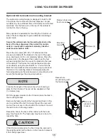
Page 10: ...d shelf space for keeping your mugs chilled The quarter barrel must set on the floor it cannot fit on the shelf see Figure 16 Be sure the white floor plate is in the bottom of the interior compartment before positioning the barrel Figure 16 Half barrel keg Installed upper shelf above barrel Figure 15 Quarter barrel Figure 17 If you are using a half barrel keg or 2 1 6 barrels place the two shelves...

Page 11: ... If it becomes difficult to breathe and or your head starts to ache a high concentration of carbon dioxide may be present Leave the area immediately The CO2 tank must always be connected to the regulator Never connect the tank to the keg The CO2 tank must be securely mounted in the upright position Secure it with the chain pro vided Never drop or throw the CO2 tank Keep the CO2 tank away from heat...

Page 12: ...r Keg Coupler Keg Coupler Single Dispense Tower Double Dispense Tower A C Hose clamps use for connections and A C Hose clamps use for connections and A A Single Dispense Tower Kit Connect to etc A A Double Dispense Tower Kit Connect to etc Figure 18 Figure 19 Figure 20 Figure 25 Figure 26 Figure 28 Figure 24 Figure 22 Figure 23 USING YOUR BEER DISPENSER ...

Page 13: ...ound the tower and place the grate in the sump 5 Mount the regulator to the CO2 tank connection Note that the regulator has left hand threads and has to be turned counterclockwise to tighten Tighten with the adjustable wrench or the 11 8 open end wrench 6 Connect the red air line s from the regulator to the large air line fitting on the keg coupler with a large hose clamp connection 7 Connect the ...

Page 14: ...s on the keg coupler and turn clockwise until the coupler stops about 90 Push down and twist the top of the coupler clockwise to allow gas to enter the keg Figure 32 The chain is fastened and taped to the top of the interior liner Remove the tape and secure the CO2 tank in place in the back right corner Loop chain around top of tank and connect with S hook Push faucet handle back toward tower to c...

Page 15: ...racket to the back of the cabinet The bracket can also be fastened to adja cent cabinetry using the provided 10 x 3 4 wood screws Mark the hole locations where required using a pencil and the slots in the mounting bracket Drill appropriate pilot holes depending on the material you are mounting to and secure the bracket per the above instructions Consider the length of the red air line when choosin...

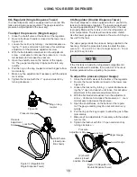
Page 16: ...nut with the 1 2 open end wrench by turning clockwise CO2 Regulator Single Dispense Tower Your beer dispenser comes equipped with a 5 pound CO2 tank and a single gauge regulator The gauge reads the pressure being supplied to the beer keg To adjust the pressure Single Gauge 1 Close the shutoff valve at the bottom of the regulator 2 Be sure the faucet handle is closed on the tower see Figure 32 3 Lo...

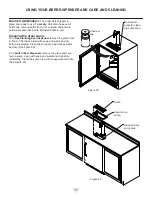
Page 17: ...e drain sump On a free standing beer dispenser remove the grate from in front of the tower clean with soap and water and dry before reinstalling Clean the sump area with soapy water and dry See figure 39 On a built in beer dispenser remove the grate and coun ter top sump clean with soap and water and dry before reinstalling Clean the sump area with soapy water and dry See Figure 40 Grate Counter t...

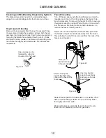
Page 18: ...ble faucet to tower be sure faucet is in off position and turn on gas valve Figure 43 Figure 44 After removing the handle the shaft will slide out the back of the faucet Unscrew knurled cap on faucet body and remove handle assembly Place pin on wrench into hole in faucet collar CARE AND CLEANING Keg Coupler Cleaning Remove the keg coupler from the keg if necessary Close the gas valve s below the r...

Page 19: ...pliance Damage to the grille can occur 3 Periodically clean the interior of the appliance as needed In the Event of a Power Failure If a power failure occurs try to correct it as soon as pos sible Minimize the number of door openings while the power is off so as not to adversely affect the appliance s temperature Front Grille Be sure that nothing obstructs the required air flow open ings in front ...

Page 20: ... unit 14 Remove the rear access cover see Figure 48 and use a brush and vacuum to clean dirt and debris from the machine compartment 15 Thoroughly clean the rear access cover and re install on the unit 16 Wipe down all interior surfaces with anti bacterial cleaner to be followed with clean rinse water to remove any residual chemicals which could cause staining Do not use any abrasive cleaners or s...

Page 21: ...emicals 19 Thoroughly clean the exterior with a cleaner approved for stainless steel Do not use any abrasive cleaners or scouring pads 20 Any mounting hardware fasteners that are showing signs of corrosion should be replaced 21 Once the exterior has been thoroughly cleaned you may want to apply a coating of car wax to help protect against spotting from moisture dirt and debris that may accumulate ...

Page 22: ... replaced Frequency of cleaning will depend upon the installation location environmental and usage conditions Choosing a Cleaning Product The choice of a proper cleaning product is ultimately that of the consumer and there are many products from which to choose Depending upon the type of cleaning and the degree of contamination some products are better than others Typically the most effective and ...

Page 23: ...e compartment minimize door openings for the next 12 hours to allow contents to pull down to compartment set temperature 6 Maintaining a relatively full storage compartment will require less appliance run time than an empty compart ment 7 Ensure door closing is not obstructed by contents stored in your appliance 8 Allow hot items to reach room temperature before plac ing in product 9 Minimize door...

Page 24: ...t stabilized Excessive usage or prolonged door open ings Airflow to front grille blocked Door gasket not sealing properly Adjust temperature colder Allow 24 hours for temperature to stabilize Allow temperature to stabilize for at least 24 hours Airflow must not be obstructed to front grille See clearances on page 4 Replace door gasket Appliance too cold See Adjusting the Temperature on page 9 Cont...

Page 25: ...0703 562 802 3488 Entire Product Limited One Year Parts and Labor Warranty Twin Eagles warrants that it will supply all necessary parts and labor to repair or replace in the end user s home or office any component which proves to be defective in ma terial or workmanship subject to the condition and exclu sions stated below for a period of one year from the date of purchase by the end user Addition...

Page 26: ...26 ...

Page 27: ...27 13259 http www twineaglesgrills com contactus shtml ...

Page 28: ...28 13259 41014795 rev A 1 23 17 ...

Reviews: