background image

NVMS 

User Manual 

21


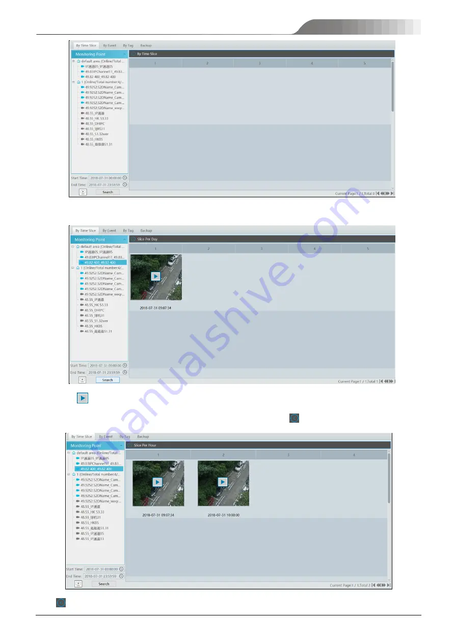
Select channel (or monitoring point), set the start time and the end time, select the record source and then click [Search].   


Click 

  to play the record. 


Double click the image to switch to slice search mode by day. In the above interface, click 

  to switch to slice search mode by hour.   


Click 

  to return to slice search mode by day; double click an image to switch to slice search mode by 5 minutes.   

Summary of Contents for TD-A510-MTC-E

Page 1: ...NVMS 5000 NVMS Management Server User Manual...

Page 2: ...ain the usage of our product The ownerships of trademarks logos and other intellectual properties related to Microsoft Apple and Google shall belong to the above mentioned companies All examples and p...

Page 3: ...nd 2 this device must accept any interference received including interference that may cause undesired operation CE Marking The products have been manufactured to comply with the following directives...

Page 4: ...erver 8 4 Live View 10 4 1 Live View 10 4 1 1 View Mode Setting 11 4 1 2 Monitoring Point View 11 4 1 3 Channel Group View 12 4 1 4 Plan View 13 4 2 View Control 13 4 3 Snapshot 14 4 4 Multi Screen Vi...

Page 5: ...ation 48 9 Account and Permission 49 9 1 Create Account 49 9 2 User Permission Settings 49 10 Operation and Maintenance Management 51 10 1 Check and Export Log 51 11 Local Configuration 52 11 1 1 Syst...

Page 6: ...NVMS User Manual 13 Web Client 61 13 1 Operating Environment of Web Client 61 13 2 Start IE Client 61 14 Troubleshooting 63 15 Specifications 65...

Page 7: ...control and focus control support setting and calling preset and cruise Support listen two way talk and broadcast Support record search playback and downloading from device and control center Support...

Page 8: ...nection is normal 1 2 Rear Panel Instructions No Description No Description 1 Mouse or keyboard port 9 Central bass orange 2 VGA port 10 Rear speaker black 3 DVI port 11 Optical SPIDF out port 4 HDMI...

Page 9: ...Password or Auto Login as needed Click Login If you forget the password please click Forgotten password Then a small window will appear You can get the IP address of the authentication server the conf...

Page 10: ...gement To set TV wall and decoding videos on TV Walls Resource Management To add modify or delete areas devices or servers Account and Permission To add modify or delete user account and set permissio...

Page 11: ...local network as shown below Check the device and allocate the transfer server storage server area for it After that click OK Note The default media transfer server and storage server can be selected...

Page 12: ...erface Enter the device ID set in the DVR NVR or IP camera and choose the protocol If the DVR NVR is needed to add please go to Network Server interface of the DVR NVR Check Enable enter the IP addres...

Page 13: ...rameters of the device can be set up Different devices have different menus Please configure the device according to the corresponding user manual 3 4 Area Setting Go to Home Area Setting interface as...

Page 14: ...of the front end devices sent by the client or storage server is transferred by the media transfer server to the front end devices Go to Home Add Edit or Delete Device Media Transfer Server Click Add...

Page 15: ...add or manually add storage servers Select the Quickly Add tab and click Refresh to quickly search servers in the same local network Check the desired servers and click OK to save the settings Select...

Page 16: ...interface you can view the captured pictures by choosing cameras and setting the start time and the end time Additionally the captured time also can be exported by U disk Record management Click to g...

Page 17: ...Setting Users can select the common display mode and self define the display mode through the buttons on the toolbar To customize the display mode Click on the toolbar Enter screen display name and se...

Page 18: ...hannel Group View After the channel group is set successfully See Configure Channel Group go to live view interface as shown below Choose a channel group and drag it to a window to view The channels i...

Page 19: ...ding view window Enter the view name and click OK to set view plan Select screen display mode and then drag monitoring points or channel group to each window Click View on the left menu and then right...

Page 20: ...k on the live view window and then choose Audio On or click on the toolbar of the window to enable audio Note Only one audio can be enabled at the same time If the audio of one channel is enabled the...

Page 21: ...face 4 5 Talkback In a live view window click on the toolbar of this window or select Start Talkback on the pop up menu by right clicking to enable talkback Note Since the software only allows enablin...

Page 22: ...a channel is recording closing viewing will stop recording 5 1 2 Schedule Recording Go to Home Configure Record To set schedule recording select the channel stream type and schedule Then Click Apply...

Page 23: ...n below Select alarm type enable record set linakage channel and set schedules Click Apply to save the settings 5 2 Record Playback In the main menu interface click Record Playback to go to record pla...

Page 24: ...back Window Button Description Button Description Stop viewing Zoom in Audio on off Zoom out Snapshot Fit to window Button Descriptions of Area 2 Button Description Screen display mode button 1 4 9 16...

Page 25: ...g or double click a desired channel to play or click Search to search the record files and then click to play Playback record type includes manual recording motion detection recording schedule recordi...

Page 26: ...playing window All cameras record information can be viewed at the same time When playing record file in synchronous mode or asynchronous mode clicking or will be useless unless all the playback windo...

Page 27: ...record source and then click Search Click to play the record Double click the image to switch to slice search mode by day In the above interface click to switch to slice search mode by hour Click to...

Page 28: ...nterface click to return to slice search mode by hour 5 2 5 Playback by Event Go to Home By Event interface as shown below Select the desired monitoring point set the record source the start time and...

Page 29: ...esh to search the added tags Click in the playback column to play the record 5 3 Backup In the main menu interface click Backup to go to the backup interface The setting steps are as follows Select th...

Page 30: ...NVMS User Manual 24...

Page 31: ...ettings There is a default alarm server Go to Home Add Edit or Delete Device Alarm Server interface to view the online status of the alarm server If it is not online please check its network connectio...

Page 32: ...tput and TV Wall are the same with each other Here take record linkage for example to introduce the setting steps Check the selectable channel and click to select the channel check the selected channe...

Page 33: ...Manual 27 Click or to play the record or captured images click to delete alarm information 6 1 4 Alarm Log Query Alarm logs can be searched and exported by going to Home Alarm Center Alarm Log Query...

Page 34: ...Click to play the record click to open the snapshot search window as shown below 6 2 Alarm System 6 2 1 Add Alarm Host Go to Home Add Edit or Delete Device Alarm Host interface Click Add to prompt the...

Page 35: ...me Alarm System Subsystem interface as shown below Arm Disarm Clear Alarm or Refresh Status can be operated in this interface 6 2 3 Zone Go to Home Alarm System Zone Bypass Bypass Recovery and Refresh...

Page 36: ...NVMS User Manual 30...

Page 37: ...t parent e map and map type Then click OK to save the settings 7 1 2 Add Hotspot The hotspots include monitoring points sensors subsystem zone and door Drag a hotspot to the corresponding area on the...

Page 38: ...NVMS User Manual 32...

Page 39: ...er server The decoding output is a standard video signal The decoder is necessary for decoding videos on the TV wall Go to Home Configure Device Decoder interface The setting steps of adding decoders...

Page 40: ...all Management TV Wall System Setting Decoder Bind Configuration Then click to bind decoder and TV wall See Decoder Bind for details 8 3 TV Wall Management Go to Home TV Wall Management Edit TV Wall 8...

Page 41: ...wall window Click Initialize to create TV wall layout Merging Splitting Merging drag on the screen and then release The Merge button will be shown Click it to merger these small windows Splitting sele...

Page 42: ...list is the binding decoder of this TV wall Drag the outputs to windows on the right in sequence and then click Save to save the settings To modify TV wall Click beside the TV wall name enter the new...

Page 43: ...Go to Home TV Wall Management TV Wall System Setting interface as shown below In this interface decoder bind can be set up Decoder bind configuration modify the binding state between decoder and TV wa...

Page 44: ...th TV wall Go to TV Wall Setting interface as shown below Drag the outputs of the decoder to the window on the right and save them to complete output bind 8 3 2 TV Wall View Create Plan Go to Home TV...

Page 45: ...pectively to decode image Toolbar Menu 1 Screen mode 1 4 9 16 screen mode is optional 2 Open Window Click Popup Enable and then drag on a window to open a small window on it Click Popup Disable to sto...

Page 46: ...16 screen mode is optional 2 Zoom in out if the current screen mode is multi screen display mode click Zoom In to zoom in the current image Click Zoom Out menu again to restore to the previous status...

Page 47: ...decoding window Direction control zooming and focusing Iris control speed preset and cruise calling can be operated through this control panel 6 Stop Decoding click it to stop decoding the current ima...

Page 48: ...NVMS User Manual 42 Select the merged window and click Split to restore the window to its previous status...

Page 49: ...Auto Switch Group 2 Create Auto Switch Group Click Auto Switch Group under the screen and then click to create auto switch group Select Auto Switch Window to select the window group Click Monitoring...

Page 50: ...o switch 4 Modify or delete auto switch Right click the auto switch name and then select Modify or Delete to modify or delete the auto switch Note If there are overlapped auto switch window in a plan...

Page 51: ...ch plan needs to modify please stop it first 8 3 3 Decoder Input Go to Home TV Wall Management Decoding on TV Wall Decoder Input Drag an input to a window to execute decoding 8 3 4 Playback Playback o...

Page 52: ...the above buttons Right click menu 1 Screen mode 1 4 9 16 screen mode is optional 2 Zoom in 3 Save as an alarm window 4 Save as preview window the current channel or the historical channel is optiona...

Page 53: ...ask Configuration Click behind the TV wall name Select plan name enter task name set run time and enable plan task Click to start the task Click the Stop button to stop this task Modify or delete task...

Page 54: ...onfiguration Go to Home TV Wall Management TV Wall System Configuration interface as shown below In this interface channel number and decoder bind can be set up Channel number configuration set the ch...

Page 55: ...lick Add to prompt an adding user window as shown below Enter user name and password Then select permission group it must be set in advance Binding MAC address or remark can be filled in as needed Aft...

Page 56: ...NVMS User Manual 50 Enter permission group name Select system permission operation permission and area permission as needed Click to modify the permission group click to delete the permission group...

Page 57: ...me Operation and Maintenance Management Click the Check and Export Log tab as shown below All types of logs can be searhed and exported here Select the log type set the start time and the end time and...

Page 58: ...s system support CPU and memory overload protection When the system overloads the server will restrict the new live view and playback operation and the overload tip will prompt Go to Home Local Config...

Page 59: ...5 Server Port Settings In this interface users can enable or disable each server service as needed The port of each server also can be changed 11 1 6 System Time Settings In this interface time zone a...

Page 60: ...the same local network as shown below Click the Manually Add tab to manually add the IP address and port of the server 12 1 People Counting 12 1 1 Task Management Go to Home People Counting Task Manag...

Page 61: ...tatistics Before setting summary statistics please set E Map by going to Home E Map Configure E Map first Drag the camera with the people counting function to the specified area Then return to the sum...

Page 62: ...which can be shown in histogram or curve chart 12 2 Access Control Management Before using access control management system please make sure whether the access server is online Go to Home Resource Ma...

Page 63: ...Open the Door Go to Home Access Control Management The access control devices are listed as shown below Double click a device to display the doors controlled by this device Double click a door icon to...

Page 64: ...up 12 2 3 Log Query Go to Home Access Control Management Log Query The alarm information of the access control devices in a long period of time can be searched in this interface 12 2 4 E Map ACS Befor...

Page 65: ...12 3 Attendance Management 12 3 1 Alarm Linkage Go to Home Attendance Management Alarm Linkage In this interface the access control device linkage configuration can be set up 12 3 2 Log Query Go to Ho...

Page 66: ...NVMS User Manual 60...

Page 67: ...ts and configure antivirus and firewall to allow the installation of the plugin files 13 2 Start IE Client Before starting IE client make sure all servers must be started first Login Input the IP addr...

Page 68: ...configuration client click Return to Monitor to go to the web monitor client In the web monitor client or configuration client click the platform logo to return to the platform interface The operation...

Page 69: ...ck the Service tab to check 4 The device information cannot be seen or the device is offline after the user logins to the monitor client 1 Please checkup whether this user account is anadministrator a...

Page 70: ...the CPU occupancy rate of the client platform is 100 or there still has usable memory This situation will not emerge when the CPU occupancy rate is less than 75 and there still has usable memory 2 Pl...

Page 71: ...CH Max number of transfer server access 32 transfer servers Max number of storage server access 128 storage servers Device Group Support Max number of users 256 users Simultaneous Online users 256 us...

Reviews: