TVLogic SWM-171A Operation Manual Download Page 17

32  Multi Format LCD Monitor   

 Multi Format LCD Monitor   33

SWM-171A

SWM-171A

SWM-171A

SWM-171A

SDI A

SDI A

SDI A

SDI A

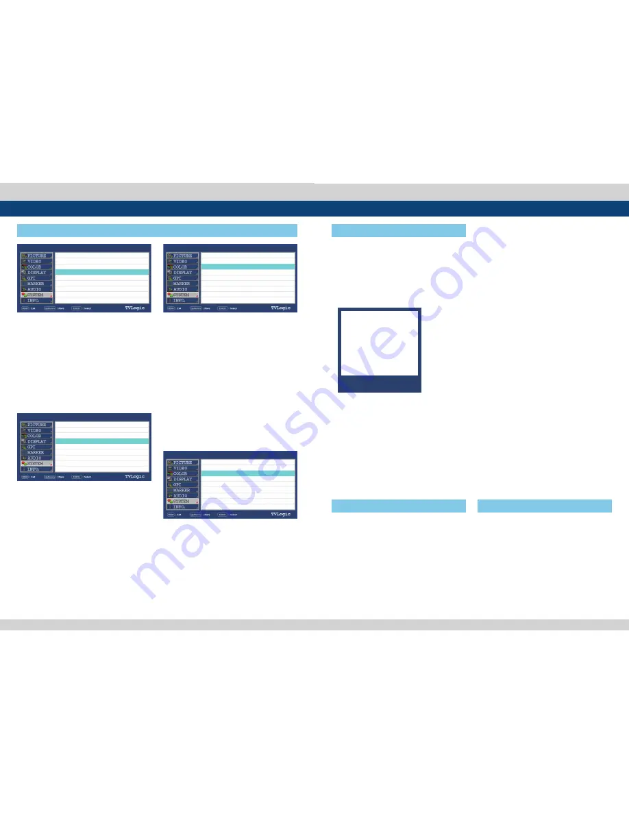
[1] Firmware Upgrade

[2] Color Calibration

6. Firmware Upgrade & Color Calibration


The USB portable storage device (Thumb  

  drive) is needed for Firmware Upgrade.


Select the PAGE III of [SYSTEM] menu to  

 activate.

1. Connect the USB to the USB Slot on the    

    front of the monitor.

2. Set the [S/W UPGRADE] as [ON].

3. Search the USB.

4. The [S/W UPGRADE START] activates when  

    the USB connection is completed. 


The Color Probe is need for Color  


 Calibration.


 Available Color Probe : K-10, Eyeone    

  Display Pro and Specbos 1211.


Select the PAGE III of [SYSTEM] menu to  

 activate.

1. Connect the Color Probe to the USB Slot on  

    the front of the monitor.

2. Set the [DEVICE] as the Color Probe which  

    will be connected.

3. Set the [Color Calibration] as [On].

4. Then the USB Color Probe is searched    

    automatically.

5. The [Color Calibration] activates when the  

    USB connection is completed. 

5. Select the [S/W UPGRADE START] to start  

    the firmware update.

* While the Upgrade is conducting, the  


   monitor screen turns off and the monitor   

  stops functioning. 
* When the Upgrade is completed, the  


   monitor  reboots. 
* The Upgrade process takes about 30  


   minutes according to the Firmware type.

- During the Upgrade, do not turn off or    

  control the product.

- Before the Upgrade, a message is indicated  

  as below for 5 seconds.

* The firmware update may tak 30 minutes.  

  Please do not  turn off the monitor while

  updating.

6. Set the value of [TARGET LUMINANCE], [K-10  

    CHANNEL] and [COLORSPACE].

7. Select the [CALIBRATION START] to start the  

    calibration. 

* After the calibration starts, various patterns  

   come on the screen and conduct the color  

 calibration. 
* The Color Calibration takes about 10~20    

 minutes.

1080/60i

1080/60i

1080/60i

1080/60i

PAGE VI >> PAGE V

COPY DATA

CAL. LOG COPY START

S/W UPGRADE

S/W UPGRADE START

PAGE III >> PAGE VI 

DEVICE

COLOR CALIBRATION

TARGET LUMINANCE
K-10 CHANNEL   00:
COLORSPACE
CALIBRATION START
MEASUREMENT

PAGE III >> PAGE VI 

DEVICE

COLOR CALIBRATION

TARGET LUMINANCE
K-10 CHANNEL   00:
COLORSPACE
CALIBRATION START
MEASUREMENT

PAGE VI >> PAGE V

COPY DATA

CAL. LOG COPY START

S/W UPGRADE

S/W UPGRADE START

OFF

OFF

K-10

OFF

80cd/m

2

REC-709

Y:000.00  x:0.000  y:0.000   

K-10

ON

80cd/m

2

REC-709

Y:000.00  x:0.000  y:0.000   

OFF

ON

7. Button Functions


This product is capable of processing    

  various input signals.


The signal input settings are as follows.

1. Press the MENU button on the back of    

  the product for more than 1.5 seconds and  

  activate the menu below.

2. Press the MENU button to activate the OSD  

 menu.


 When the FUNCTION button is set to    

 ASPECT

1. Four different aspect modes are available.

  When the input signal is SDI -A/B,  


  Composite 1/2/3 or S-Video and the input  

  signal format is SD :

   1) 4:3 mode : Cuts the sides of the original  

  image to fit to 4:3 aspect ratio.

    2) 16:9 mode : Stretches the image in “1) 4:3  

  mode” to fit to 16:9 aspect ratio.

    3) 4:3 Ex mode(Extend) : Extends the image  

  vertically without altering the source image.

    4) 16:9 Ex mode(Extend) : Stretches the    

  image in “3) 4:3 mode(extend)” to fit to 16:9  

  aspect ratio.     

* NTSC and PAL signals are known to be 4:3  

  aspect ratio signals, but their aspect ratio  

  is not exactly 4:3. Therefore, select “1) 4:3  

  mode) to display the exact 4:3 aspect ratio,  

  select “3) 4:3 mode (extend)” to display the  

  image without altering the source image.

* ASPECT button lamp status: 1 - 1)/3) Off, 2 -  

  2)/4) : On.

2. When the input signal is DVI DIGITAL or    

  HDMI mode, all “1 – 1),2),3),4)” display the  

  image in 4:3 and 16:9 without altering the  

  source image.

3. For the above 1), 2) aspect modes, ZERO   

  SCAN is the standard scan mode. And, in the  

  other scan modes, aspect ratio changes    

  using the image in its selected scan mode.


Used to make a quick setting of the  


  Function Key. Select the PAGE III of  


  [SYSTEM] menu to activate.


 When the FUNCTION button is set to    

 SCAN

1. Press the FUNCTION button continuously to  

  activate various scan modes.

  ZERO SCAN -> UNDER SCAN -> 1:1 SCAN ->   

  USER ASPECT -> OVER SCAN 

2. When the SCAN mode is 1:1 SCAN, Press the  

  ENTER button to rotate the position.

1. When the OSD menu is activated, this    

  button is used to confirm a chosen value (or  

 mode). 

2. May also be used to control the Bright/   

  Contrast/Chroma/Aperture value during the  

  OSD menu inactivation. 

3. Use the UP/DOWN buttons to adjust the   

  value when the desired function is selected.

[1] MENU Button

[2] Function key set

(F1/DOWN) (F2/UP)

[3] ENTER Button

SDI-A

SDI-B

DVI-DIGITAL

HDMI

OPTIC

NO VIDEO

Summary of Contents for SWM-171A

Page 1: ...MultiFormatBroadcast LCD Monitor Operation Manual_v2 5 SWM 171A SWM 240A SWM 320A SWM 420A SWM 460A SWM 550A ...

Page 2: ...ith the instruction manual may cause harmful interference to radio communications Operation of this equipment in a residential to correct the interference at his own expense CAUTION Change or modifications not expressly approved by the manufacturer responsible for compliance could void the user s authority to operate the equipment Disposal of Old Electrical Electronic Equipment Applicable in the E...

Page 3: ...ing In case the product needs replacement parts make sure that the service person uses replacement parts specified by the manufacturer or those with the same characteristics and performance as the original parts Use of unauthorized parts can result in fire electric shock and or other danger Upon completion of service or repair work request the service technician to perform safety checks to ensure ...

Page 4: ...r control DVI HDMI HDCP Input support DVI Digital and HDMI w HDCP inputs are available without the need of extra accessories Dual Link support Supports Dual link YCbCr RGB 4 4 4 and YCbCr 4 2 2 formats 3G support Supports 3G A B formats Auto Color Calibration support Supports Auto Color Calibration by directly connecting the color probes to the product Optical support Option Optical fiber interfac...

Page 5: ...NTER POWER USB TALLY DVI SDI A IN SDI A OUT SDI B IN SDI B OUT REMOTE HDMI ETHERNET OUT ETHERNET IN AC IN OPTIC CONNECTOR Option SWM 320A FRONT RIGHT SWM 320A REAR MENU UP DOWN ENTER POWER USB TALLY SDI A IN HDMI DVI SDI B OUT SDI B IN SDI A OUT REMOTE ETHERNET IN AC IN ETHERNET OUT OPTIC CONNECTOR Option 3 Controls Functions POWER USB TALLY SDI A IN HDMI DVI SDI B OUT SDI B IN SDI A OUT OPTIC CON...

Page 6: ...ton Used to turn power on and off USB This terminal is used to upgrade the firmware or color calibration made by TVLogic TALLY lamp LED indicating monitors current status 3 Controls Functions REAR LEFT Warning When using the product make sure to ground whenever possible before connecting the input signal cable in order to prevent any possible damage to the product or connected devices The damage m...

Page 7: ...t SWM 171A SDI A A MENU UP DOWN ENTER Button Status B Model name SWM 171A C Current input signal D Current input signal resolution 4 MainMenuWindowinforrmation A C B D SWM 171A 1080 60i SDI A PICTURE BRIGHT CONTRAST CHROMA PHASE APERTURE BACK LIGHT BLUE ONLY USER ASPECT HORIZONTAL USER ASPECT VERTICAL VIDEO DITHERING FILTER FAST MODE FORCE psf FILM MODE DETECTION SDI FORMAT SDI SAMPLING 3G FORMAT ...

Page 8: ... USER ASPECT VERTICAL Used to set the aspect ratio of VERTICAL value Control Range 720 1080 1 PICTURE SWM 171A SDI A BRIGHT CONTRAST CHROMA APERTURE BACK LIGHT BLUE ONLY USER ASPECT H USER ASPECT V 0 0 0 MIN 100 OFF 1366 1366 5 Menu Tree 4 Menu Tree Adjustment MARKER MARKER MARKER DISPLAY CENTER MARKER SAFETY AREA FIT MARKER MARKER MAT MARKER COLOR MARKER THICKNESS USER MARKER H1 USER MARKER H2 US...

Page 9: ...limited range 5 Menu Operations 2 VIDEO SWM 171A SDI A DITHERING FILTER FAST MODE FORCE psf FILM MODE DETECTION SDI FORMAT SDI SAMPLING 3G FORMAT VIDEO RANGE SELECT ON ON ON OFF ENABLE SINGLE YCbCr 444 NORMAL MODE LIMITEC EX 3 COLOR 5 Menu Operations COLOR TEMP Used to control color temperature and allow instant access to preset color temperature settings Available values are 3200K 5000K 5600K 650...

Page 10: ...atio of input signal is 16 9 See section 8 Other Functions 1 ASPECT page for more information 4 DISPLAY 5 Menu Operations SWM 171A SDI A PAGE I PAGE II HD DIPLAY MODE TIME CODE ENABLE ORBITER CIRCUIT CLOSED CAPTION 608 CHANNEL SELECT 708 SERVICE SELECT TELETEXT PAGE 16 9 VITC OFF OFF CC 1 SERVICE 1 801 SWM 171A SDI A PAGE II PAGE I H V DELAY SCAN ASPECT OFF ZERO SCAN 4 3 This product provides a RE...

Page 11: ...as the background of character Activate the same as Default mode USER TALLY The bit0 bit 1 of TSL Protocol Control Byte receives the input signal and displays Tally by user s set OFF WHITE RED GREEN BLUE YELLOW CYAN MAGENTA USER CHAR This function activates in the same way as USER TALLY and TALLY is displays by the character color USER BG This function activates in the same way as USER TALLY and T...

Page 12: ...of following packet VER Minor version number e g V5 00 VER 0 FLAGS bit 0 Clear for ASCII based strings in packet set for Unicode UTF 16LE bit 1 If set data after SCREEN is screen control data SCONTROL otherwise it s display message data DMSG bit 2 7 Reserved clear to 0 Not used SCREEN Primary index for use where each screen Index 0xFFFF is reserved as a Broadcast to all screens If not used set to ...

Page 13: ...t the color of UMD character Available colors are WHITE RED GREEN BLUE YELLOW CYAN and MAGENTA UMD BG TRANS Used to set the transparency of the UMD background Available values are SCALE DOWN OPAQUE 50 90 and 100 SWM 171A SWM 171A SDI A SDI A 5 GPI 5 Menu Operations PAGE IV PAGE I UMD CHARACTER UMD CHARACTER COLOR UMD BG TRANS PAGE III PAGE IV DHCP IP ADDRESS SUBNET MASK GATEWAY PORT NO NETWORK SET...

Page 14: ...ecomes MARKER COLOR Used to control the color of MARKER lines Available colors are white gray black red green and blue MARKER THICKNESS This item controls the thickness of the MARKER lines The degrees of thickness are between 1 and 7 MODE MARKERCLASS HD 16 9 4 3 4 3ONAIR 15 9 14 9 13 9 1 85 1 2 35 1 1 85 1 4 3 4 3ALT16 9 16 9ALT14 9 16 9ALT 4 3 AFD USER SD16 9 SD4 3 16 9 4 3 4 3ONAIR 15 9 14 9 13 ...

Page 15: ...VEL METER SIZE LEVEL METER POSITION OFF PAIR 20dB O SMALL HOR LEVEL METER POSITION Used to control the position of the Audio Level Meters Available values are HOR VER and BOT 1080 60i SWM 171A SDI A USER CONFIG SET Used to save and apply three kinds of user configuration Available modes are USER1 USER2 and USER3 Effective items for each USER1 USER2 and USER3 settings are MARKER menu of MARKER CENT...

Page 16: ...orted CALIBRATION START Used to start the calibration Set the Calibration as On The Color calibration start menu will activate after the Color Probe connection is completed MEASUREMENT Used to start the calibration Set the Color Calibration as On The Color calibration start menu will activate after the USB connection is completed COPY DATA Used to copy the files related to the calibration CAL LOG ...

Page 17: ... DATA CAL LOG COPY START S W UPGRADE S W UPGRADE START OFF OFF K 10 OFF 80cd m2 REC 709 Y 000 00 x 0 000 y 0 000 K 10 ON 80cd m2 REC 709 Y 000 00 x 0 000 y 0 000 OFF ON 7 Button Functions This product is capable of processing various input signals The signal input settings are as follows 1 Press the MENU button on the back of the product for more than 1 5 seconds and activate the menu below 2 Pres...

Page 18: ... source image 4 16 9Ex Stretches the image in 3 4 3 mode extend to fit to 16 9 aspect ratio NTSC and PAL signals are known to be 4 3 aspect ratio signals but their aspect ratio is not exactly 4 3 Therefore select 1 4 3 mode to display the exact 4 3 aspect ratio select 3 4 3 mode extend to display the image without altering the source image 2 When input signal is DVI DIGITAL or HDMI mode all 1 1 2 ...

Page 19: ...play Area 365 H X 205 V mm Input Connector 1 X DVI I DVI IN 1 X HDMI HDMI Input 2 X BNC SDI A B Channel Input 1 X OPTIC Option Optic Input Output 2 X BNC SDI A B Channel Active Through Out Input Signal 3G SDI 2 970Gbps HD SDI 1 485Gbps SD SDI 270 Mbps DVI VESA IBM Modes HDMI 480i 480p 720p 1080i 1080p VESA IBM Modes SDI Input Signal Formats SMPTE 425M A B 1080p 50 59 94 60 SMPTE 372M Dual HD SDI Y...

Page 20: ... 01 x 16 41 x 5 90 Option Box Dimensions mm inch 673 X 535 X 280 26 50 X 21 06 X 11 02 Weight 8 2Kg 18 08 lbs Basic Accessories AC Power Cord USB Cover Optional Accessories Stnad Rack Mountable Kit ND Filter Optic Module SWM 320A LCD Size 31 55 Resolution 1920 X 1080 16 9 Pixel Pitch 0 364 H X 0 364 W mm Color Depth 1 07B 10bit Viewing Angle R L U D 178degrees Luminance of white 500 cd m2 Contrast...

Page 21: ...x 10 04 Option Box Dimensions mm inch 1125 X 760 X 685 44 29 X 29 92 X 26 96 Weight 28 95Kg 63 82 lbs Basic Accessories AC Power Cord USB Cover Optional Accessories Stnad Optic Module SWM 460A LCD Size 46 Resolution 1920 X 1080 16 9 Pixel Pitch 0 530 H X 0 530 W mm Color Depth 1 06B R G B 10bit Dither Viewing Angle R L U D 178degrees Luminance of white 450 cd m2 Contrast Ratio 4000 1 Display Area ...

Page 22: ...50 59 94 60 SMPTE 372M Dual HD SDI YPbPr 4 2 2 1080p 50 59 94 60 Dual HD SDI YPbPr RGB 4 4 4 1080p 50 59 94 60 1080p psf 30 29 97 25 24 23 98 SMPTE 274M 1080i 60 59 94 50 1080p 30 29 97 25 24 24sF 23 98 23 98sF SMPTE 296M 720p 60 59 94 50 SMPTE 260M 1035i 60 59 94 SMPTE 125M 480i 59 94 ITU R BT 656 576i 50 2k Format 2048x1080p 24 24sF 23 98 23 98sF Power AC100 240V 50 60Hz Power Consumption Approx...

Page 23: ... http www tvlogic tv 12F ACE HIGH END 8 84 Gasan digital 1 ro Geumcheon gu Seoul 153 802 KOREA TEL 82 70 8668 6611 FAX 82 2 6123 3201 E mail sales tvlogic co kr 부사장 조 성 일 Mobile 010 2520 6837 153 802 서울특별시 금천구 가산동 345 4 에이스하이엔드 8차 12층 ...

Reviews: