


Multi F
orma
t L
CD M
onit
or
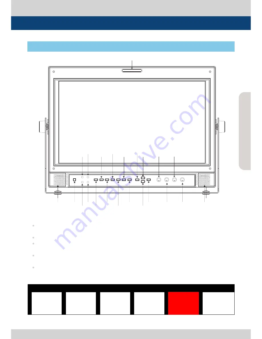
<LQM-171W-FRONT>
1. Buttons
◦
Press any button to bring up the OSD display as shown in picture 4. The selected item will display
in red. The OSD display disappears after 5 seconds if no other control is made.
◦
Each button OSD indicates feature, channel and value.
◦
For features with a channel selection, press the button repeatedly to change and select the desired
channel. Select ALL to change all channels with the same value.
◦
For the button features with individual value selections, press the button repeatedly to increase
the value of the feature by 1. The value goes back to minimum after reaching the maximum value.
◦
Rotate the SELECT ENC knob to change the value of selected item. The value will automatically
will be stored in the memory (EEPROM) once the OSD disappears.
<LQM-071W Button OSD>
Controls, Indicators and Connections
LQM-071W : FRONT
FACTORY PGM
RS 232
SDI OUT
ETHERNET
USB
SDI1/CVBS1 INPUT
SDI2/CVBS2 INPUT
SDI3/CVBS3 INPUT
SDI4/CVBS4 INPUT
AUDIO OUTPUT
REMOTE
GPI
RS 422
IN/OUT
DC 12V
INPUT
AC
INPUT
LEFT
SPEAKER
POWER
CONFIG LED
STATUS LED
USB LED
CH SEL
SDI OUT
UP F1
TALLY
ETHERNET LED
MARKER
MENU
SELECT
/BRIGHT
ENCODER
CHROMA
ENCODER
DISPLAY MODE
VOLUME
DN/F2
CONTRAST
ENCODER
MENU
ENCODER
PEAKING
WAVE INTENSITY
ENTER
RIGHT
SPEAKER
AUDIO INPUT
DP MO DE
4P
CH SEL
CH 1
PEAKING
CH 1
5
MARKER
CH 1
O FF
VO LUME
12
SDI OUT
CH1
Summary of Contents for LQM Series
Page 1: ...Multi Format LCD Monitor Operation Manual LQM Series LQM 171W multi ...
Page 2: ......
Page 27: ......


