background image

 FHD H

igh Brigh

t F

ield M

onit

or 10

• User may control various functions using  

  the MENU button and the Knob on the    

  top of the monitor.

• OSD(On-Screen Display) Menu helps to    

  use varous different functions.

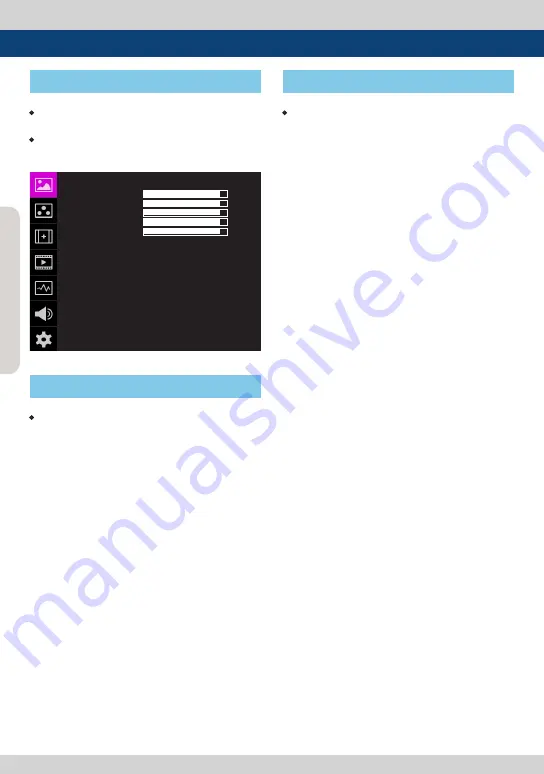
• This Picture is the menu structure for 

  F-7H mk2.

• Menu control sequence follows the order  

 below.

1. 

Press MENU button to activate the OSD  

    menu.

2. Move to a desired menu using the Knob.

3. Press the Knob to select a menu and move  

    to select a sub-menu by scrolling the Knob. 

4. Press the Knob to select the desired sub

    menu. (The selected sub-menu will be  

    highlighted)

5. Press the ENTER button or the MENU    

    button to save the new value after  


    adjusting the value by scrolling the Knob.

6.   Press MENU button to return to previous  

    menu and if there is no previous menu, the  

    OSD menu will be removed from the screen.

  [1] Menu Tree

   [2] Menu Control

  [3] Menu Control Sequence

4. Menu Tree & Adjustment

PICTURE

 같이 


   F-7H mk2

UNLOCK
REC 709
SYNCHRONIZATION
NONE01
NONE01
NONE01

BRIGHT
CONTRAST
CHROMA
SHARPNESS
PEAKING BOOST
KNOB LOCK
3DLUT LOAD
3DLUT SYNC
3DLUT IMPORT 1
3DLUT IMPORT 2
3DLUT IMPORT 3

+90
+90
+90
+12
+12

Summary of Contents for F-7H mk2

Page 1: ... High Bright Field Monitor Operation Manual_ver 1 1 F 7H mk2 F 7H mk2 AG F 7H mk2 AG is a model with Anti Glare film Haze 8 and there is no functional difference with the F 7H mk2 model except for the panel ...

Page 2: ......

Page 3: ... with the instruction manual may cause harmful interference to radio communications Operation of this equipment in a residential to correct the interference at his own expense CAUTION Change or modifications not expressly approved by the manufacturer responsible for compliance could void the user s authority to operate the equipment Disposal of Old Electrical Electronic Equipment Applicable in the...

Page 4: ...penings High voltage in the product and inserting an object can cause electric shock and or short internal parts For the same reason do not spill water or liquid on the product Do not attempt to service the product yourself Removing covers can expose you to high voltage and other dangerous conditions Request a qualified service person to perform servicing If any of the following conditions occurs ...

Page 5: ...arthing connection Unplug the power cord from the AC outlet whenhappeninganyproblemintheproduct Sudden stops excessive force and uneven floor surface can cause the product to fall from the cart The vents and other openings in the cabinet are designed for ventilation Do not cover or block these vents and openings since insufficient ventilation can cause overheating and or shorten the life of the pr...

Page 6: ...r configuration using the control knob on the top of the monitor BLUE ONLY MONO Focus Assist H V Delay Function Range Error Luma Y Zone Check Color Zebra Type Function Internal Pattern Generator 0 100 Gray ColorBar Pluge Various Markers Safety Areas Center Marker Safety Area Marker Marker Mat Marker Size Fit Marker Thickness Adjustment function Pixel To Pixel Zoom Function Used to display the orig...

Page 7: ...FHD High Bright Field Monitor 7 3 Controls Functions ALL PART PHONEJACK HDMI OUT HDMI IN KNOB MENU EXIT SOURCE USB DC POWER TALLY SDI OUT REAR TALLY SDI IN POWER BUTTON FUNCTION FUNCTION SELECT ...

Page 8: ... knob to select the main menu and the sub menus F1 F3 Button Press the button for less than 2 seconds to activate the function Press the button for more than 2 seconds to activate Function Select menu Scan Aspect H V delay etc Press the button for more than 2 seconds to indicate previously selected function Use the Knob to change the function P1 P4 Button Press the Touch Key for less than 2 second...

Page 9: ...y the manufacturer please be advised that the adapter with DC 12V 3A 6A can be compatible with the monitor Battery In Battery Power Input DC 6 8 12V SDI IN BNC Signal input terminal for HD SD 3G SDI signal SDI OUT BNC Signal output terminal for HD SD 3G SDI signal Video source from HDMI input terminal can be converted to SDI format POWER Switch Used to turn the power on and off Warning When using ...

Page 10: ...nu by scrolling the Knob 4 Press the Knob to select the desired sub menu The selected sub menu will be highlighted 5 Press the ENTER button or the MENU button to save the new value after adjusting the value by scrolling the Knob 6 Press MENU button to return to previous menu and if there is no previous menu the OSD menu will be removed from the screen 1 Menu Tree 2 Menu Control 3 Menu Control Sequ...

Page 11: ...of the monitor KNOB LOCK Locks the Knob control 3DLUT LOAD Used to apply the internally stored 3DLUT Maximum 3 x 3DLUT files can be stored The file name can be set up to 20 characters including the extension 3DLUT SYNC Used to load a list of available 3DLUT files currently stored in the FLASH MEMORY Available 3DLUT formats are Cube GV Lut Quantel Davinci and AssScratch Available sizes of the 3DLUT...

Page 12: ...tions ex Gamma or HDR curve Available modes are 2 2 2 4 2 6 PQ HLG and SLOG3 The submenus may be activated in the User1 2 3 mode only LOCAL DIMMING Used to set the Local Dimming Backlight mode Thismodeissupportedbythelocaldimming backlight model LUM 310R and does not support F 7H mk2 STANDARD Used to select the color and dynamic rage of the screen Available options are HD UHD DCI P3 PQ HLG SLog3 a...

Page 13: ...mma changes automatically according to the previously set peak luminance When it is OFF the value is set to default value of 1 2 Activates only when the EOTF is set to HLG The submenus may be activated in the User1 2 3 mode only 2 COLOR COLOR같이 F 7H mk2 STANDARD VIDEO RANGE PEAK LUMINANCE BLACK LEVEL COLOR GAMUT COLOR TEMP EOTF LOCAL DIMMING EETF HLG SG SG CAM LUT CAM LUT THROUGH UHD NARROW 100 0 ...

Page 14: ...sed to set Red Green Blue Bias or Offset mainly affects on Black level from 100 to 100 Only available in User 1 2 3 mode COLOR COPY Used to copy the R G B Gain value of pre stored color temperature settings In User mode find and select the color temperature and press the Knob to copy and apply the Gain value to GAIN RED GAIN GREEN GAIN BLUE Only available in User 1 2 3 mode 2 COLOR COLOR SPACE Use...

Page 15: ...d in the Marker menu a border line of the Safety Area will be displayed inside the Marker Images below show the difference between Fit Marker ON and OFF MARKER MAT Used to set the darkness level outside of the MARKER area from OFF transparent to 7 Black The bigger the value the darker the color MARKER COLOR Used to set the color of the MARKER lines Available colors are white gray black red green a...

Page 16: ...e MARKER menu is set to USER USER MARKER V1 Used to set the position of the first vertical marker line Displayed when the MARKER menu is set to USER USER MARKER V2 Used to set the position of the second vertical marker line Displayed when the MARKER menu is set to USER MARKER같이 F 7H mk2 ENABLE MARKER CENTER MARKER SAFETY AREA FIT MARKER MARKER MAT MARKER COLOR THICKNESS USER MARKER H1 USER MARKER ...

Page 17: ...detected when Payload signal is contained SCAN Used to change the Scan mode Scroll up and down using the Knob and the mode will chang as the following sequence Zero Scan Over Scan Pixel To Pixel User Aspect USER ASPECT User can control the aspect ratio by adjusting width and height of the display See section 7 Other Functions 1 User Aspect for more information ASPECT Used to change the Aspect Rati...

Page 18: ...n full screen e g 10 Zoom If the input signal s resolution is 1920 x 1080 only 90 1728 H x 972 V of the image would be shown on full screen without the remaining 10 192 H x 108 V of the image See section 7 Other Functions 4 Zoom for more information ZOOM SPLIT Used to magnify the image Usedtozoomthespecifiedareasequentially Designable areas are Left Top Right Top Left Bottom Right Bottom and Cente...

Page 19: ... in an image Available values are from 0 to 100 Larger the value the more sophisticated the detail detection Designated color is displayed when the difference of the edges exceeds the previously set value This feature is available only when the FOCUS ASSIST mode is activated DSLR Select the DSLR camera to be used with the monitor Available mode is CANON 7D DSLR cameras screen size and aspect ratio...

Page 20: ...vel as Low to inactivate the Tally Low Set the level as Low to activate the Tally and set the level as High to inactivate the Tally SCR TALLY COL Used to set Tally color Available colors are Red Green and Yellow LOW BAT DIS Used to set Low Battery Display function When the battery becomes weak Low Battery sign is indicated on the OSD 4 VIDEO 5 Menu Operations VIDEO이 F 7H mk2 DSLR DSLR SCALE TIMECO...

Page 21: ...Blend when the main OSD overlaps the waveform vectorscope And turns back to Opaque when the main OSD disappears SIZE Adjust the size of the Waveform or Vectorscope Can select among NORMAL and LARGE See section 7 Other Function 2 Waveform Vectorscope for more information LINE WAVEFORM This item is utilized to display the entire data or one line data on the Waveform SEL LIN POS Used to select specif...

Page 22: ...Y level to be colored Yellow Pink and Cyan in Color Pattern mode or to set Y level zone to be displayed with diagonal lines in Zebra Pattern mode simply by scrolling the Knob Available values are 0 100 See section 7 Other Function 5 Luma Y Zone Check for more information 5 WAVEFORM 5 Menu Operations RANGE ERROR Used to set whether or not to activate Y MAX Y MIN C MAX C MIN Y PICTURE BLINK and C PI...

Page 23: ...nk on the screen and be displayed in red on the Waveform C MIN Used to set the minimum chroma C level from 0 to 255 Pixels with values exceeding the max Y level will blink on the screen and be displayed in red on the Waveform 5 WAVEFORM 5 Menu Operations Y PICTURE BLINK Used to set whether or not to blink pixels with values exceeding Y MAX and Y MIN C PICTURE BLINK Used to set whether or not to bl...

Page 24: ...right of the screen horizontally 16 CH VER Displays 8 channels on center left and 8 channels on top right of the screen vertically LVM DISPLAY Used to set the display method for audio level meter Available modes are Group and Pair In the HDMI mode the mode is set to Pair LVM REFERENCE Display the default audio level meter value Available options are 18dB and 20dB Audio level meter within selected ...

Page 25: ... minimum value when the time set in the still image output is exceeded When video is output or the MENU button is pressed the LUMINANCE is reset to the original value Settable options are ON 5MIN 10MIN 20MIN and 30MIN In the Function Key the screen can be turned ON OFF immediately by user s choice S W UPGRADE Used to upgrade the firmware using USB Thumb drive See section 7 Other Functions 13 Firmw...

Page 26: ...NU EXIT button on the front of the monitor for more than 2 seconds and activate the OSD menu as shown on the below 2 Input resolution displays on the bottom of the OSD screen 3 Press the MENU EXIT button again to remove the OSD menu from display If no image displays after selecting the desired input mode check and make sure that your connection is not lost or disconnected 2 Function Key Set Button...

Page 27: ... activation press the Knob to begin controlling Adjust the ratio using the knob Adjust the ratio using the Knob Control range for width 0 1920 Control range for height 0 1080 The size adjusted picture always stays in the center of the screen The size can be adjustable with 2 increment and decrement To adjust the 16 9 aspect ratio of 1920X1080 resolution into 2 35 1 aspect ratio adjust the width an...

Page 28: ...pes are displayed according to SD or HD input signals 100 and 75 scales are indicated on the Vetorscope The Waveform Vectorscope function can be used only when the input signal is YUV In the case of RGB input Waveform RGB is supported Available modes in the YUV signal Waveform Y Vectorscope Waveform Wide Waveform Y Cb Cr RGB Conv Wave_Vector Vector_YCbCr Full Waveform Y Full Vectorscope Waveform C...

Page 29: ...or Line Waveform Select Line Position and use the Knob to select a vertical line Selected line is indicated in White on the screen Control range varies according to the resolution of the input SDI signal PAL 0 625 NTSC 0 525 720p 0 750 1080 i p 0 1125 Selected line is indicated on the screen Used to magnify the input signal from 0 to 90 Supports Zoom Width Scroll Zoom Height Scroll function Zooms ...

Page 30: ...a better performance in setting the exposure when shooting with vDSLR cameras Zebra Pattern Type Displays the pixels with designated Luma Y levels with zebra pattern Y 100 Pixels with Y level over 100 turn to red diagonal stripes Y 0 Pixels with Y level under 0 turn to green diagonal stripes User defined Y levels are displayed as black diagonal stripes Factory Default Y level is 70 and the pixels ...

Page 31: ...Mono Background image is mono type Color Background image is original color type 7 RangeError Pixels with Y or C levels exceeding the designated levels of Y MAX Y MIN C MAX and C MIN shall blink Analyzes the input signal s Luma Y and chroma information C and if the input signal exceeds the designated minimum value and maximum value the pixel shall blink This function is to help the user to easily ...

Page 32: ...ll screen In Recording mode of CANON 5D Mark II the output resolution is SD 480p Although it is SD the real output resolution is 640x390 not 720x480 Note 1 When you compare the circle chart or the camera shooting chart with DSLR connected monitor HDMI and HDMI to SDI Conversion connected monitor The function of Live Rec 16 9 mode should be selected to compare circle and it is equal to its actual I...

Page 33: ...or 60p is specified in the specification of the cameras the actual recording or HDMI output format would be 59 94i or 59 94p 10 SDI To HDMI Conversion Out Output Format Input Format 1080p50 1080p60 480i NTSC 576i PAL 480P 576P 720P50 720P59 94 720P60 1080i50 1080i59 94 1080i60 1080p24 1080p25 1080p30 1080psF24 1080p50 1080p59 94 1080p60 Output Format Input Format 1080p50 1080p60 480i NTSC 576i PAL...

Page 34: ...e rear Screen TALLY Operating Level Used to set the input level of Tally operation Open Low less than 0 6V High more than 2 5V High Set the level as High to activate the Tally and set the level as Low to inactivate the Tally Low Set the level as Low to activate the Tally and set the level as High to inactivate the Tally Screen TALLY Color Used to set Tally color Available colors are Red Green and ...

Page 35: ...nu 1 Connect the USB to the USB Slot on the front of the monitor 2 Select what to update among CPU FPGA ALL in S W UPGRADE 3 When the USB connection is completed the S W upgrade starts and the progress displays on the bottom left side of the screen 4 If the USB doesn t connect properly or there is no fi le in the specifi ed location the error message will be displayed on the bottom left side of th...

Page 36: ...0x1080 60i 1080 29 97PsF 1920x1080 60i 1080 24p 1920x1080 24p 1080 25p 1920x1080 25p 1080 29 97p 1920x1080 30p 1080 30p 1920x1080 30p 1080 50i 1920x1080 50i 1080 50p 1920x1080 25p 1080 59 94i 1920x1080 60i 1080 60i 1920x1080 60i 1080 59 94p 1920x1080 60p 1080 60p 1920x1080 60p PC 640 x 400 70Hz 640x400 70p 640 x 480 60Hz 640x480 60p 640 x 480 75Hz 640x480 75p 800 x 600 60Hz 800x600 60p 800 x 600 7...

Page 37: ...psf 1280x720 50 59 94 60P YCbCr 4 2 2 10bit Input Signal Interfaces Signal Format HDMI DP HD SDI single link 1080p 60 59 94 50 30 29 97 25 24 23 98 1080i 60 59 94 50 720p 50 59 94 60p 480i 60 576i 50 480p 60 576p 50 RGB 4 4 4 8bit 10bit 12bit YCbCr 4 4 4 8bit 10bit 12bit YCbCr 4 2 2 8bit 10bit 12bit Input Signal Interfaces Signal Format 3G SDI 3G SDI A B single link 1920x1080 60p 59 94p 50p YCbCr ...

Page 38: ...p 576i 576p 720p 1080i 1080p SDI Input Signal Formats SMPTE 425M A B 1080p 60 59 94 50 30 29 97 25 24 23 98 30sF 29 97sF 25sF 24sF 23 98sF 1080i 60 59 94 50 SMPTE 274M 1080i 60 59 94 50 1080p 30 29 97 25 24 24sF 23 98 23 98sF SMPTE 296M 720p 60 59 94 50 SMPTE 125M 480i 59 94 ITU R BT 656 576i 50 Audio In SDI Embedded Audio Group Ch Selectable Audio Out External Output Port 3 5m Phone Jack Power DC...

Page 39: ...1 Ball Head forVFM 058W 055A F 7H mk2 BH 2 Ball Head forVFM 058W 055A F 7H TH Mount 05 Camera Mount forVFM 056WP 058W 055A F 7H BB F7H S Battery Bracket for F 7H Sony NP F770 F970 BB F7H C Battery Bracket for F 7H Canon BP Series BB F7H P Battery Bracket for F 7H Panasonic CGA VB Series ...

Page 40: ...or F 7H Sony BP U30 U60 BB F7H E Battery Bracket for F 7H Canon LP E6 Series DSLR EOS 5D 7D BB F7H B Battery Bracket for F 7H Panasonic AF 100 V Mount F7H C Battery Adapter for F 7H V Mount F7H Battery Adapter for F 7H IDXV Mount Plate AB mount F7H AP G Mount F7H EMEA Anton Bauer Gold Battery Adapter for F 7H ...

Page 41: ...C 075A SRM 074W N F 7H CoilType D Tap S cable D Tap Adapter forVFM 056WP 058W 055A LVM 074 070C 075A SRM 074W N F 7H short 17 length D Tap L cable D Tap Adapter forVFM 056WP 058W 055A LVM 074W 070C 075A SRM 074W N F 7H Long 29 length OPT AF F7H External Acrylic filter for F 7H HDMI BKT F7H HDMI Bracket for F 7H CC F7H Pelican Case 1170 for F 7H ...

Page 42: ...FHD High Bright Field Monitor 42 MEMO ...

Page 43: ......

Page 44: ...ISIT http www tvlogic tv 12F ACE HIGH END 8 345 4 Gasan dong Geumcheon gu Seoul 18590 KOREA TEL 82 70 8668 6611 FAX 82 2 6123 3201 E mail sales tvlogic co kr 부사장 조 성 일 Mobile 010 2520 6837 153 802 서울특별시 금천구 가산동 345 4 에이스하이엔드 8차 12층 ...

Reviews: