background image

30  Multi Format LCD Monitor   

6. Firmware Upgrade  &  Color Calibration

[2] Color Calibration

The K10-Probe(USB) is needed for Color  

 Calibration.

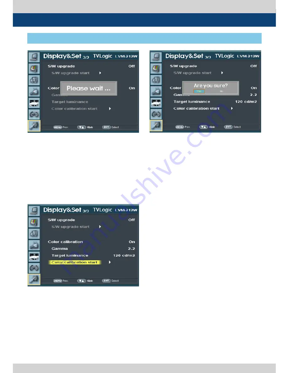
Select the [Display&Set ] menu to activate

- Connect the K10 Probe to the USB Slot on the  

  front of the monitor.

- Set the [Color calibration] as [On].

- Then the USB Color Probe is searched  


 automatically. 

- After [Color calibration start] is selected, the  

  message window comes on. Select the [Yes]  

  to proceed the Uprgrade.

* After the calibration starts, various patterns  

  come on the screen and conduct the color  

 calibration.

*When the Color Calibration is completed, the  

  normal picture is shown on the screen. The  

  Color Temperature is set as 6500K.

* The Color Calibration takes about 30  


 minutes.

- The [Color calibration] activates when the  

  USB connection is completed.

* If the feature does not activate, disconnect  

  the USB and re-connect to the monitor.    

  Repeat the same process in 5 seconds.

- Set the value of [Gamma] and [Target  


 luminance].

Summary of Contents for LVM-174W

Page 1: ...MultiFormatBroadcast LCD Monitor LVM 174W LVM 212W Operation Manual_v1 2 ...

Page 2: ......

Page 3: ...cordance with the instruction manual may cause harmful interference to radio communications Operation of this equipment in a residential to correct the interference at his own expense CAUTION Change or modifications not expressly approved by the manufacturer responsible for compliance could void the user s authority to operate the equipment Disposal of Old Electrical Electronic Equipment Applicabl...

Page 4: ... on the product Do not attempt to service the product yourself Removing covers can expose you to high voltage and other dangerous conditions Request a qualified service person to perform servicing If any of the following conditions occurs unplug the power cord from the AC outlet and request a qualified service person to perform repairs a When the power cord or plug in damaged b When a liquid was s...

Page 5: ...re to follow the manufacturer s instruction Use only the mounting hardware recommended by the manufacturer When relocating the product placed on a cart it must be moved with the utmost care Sudden stops excessive force and uneven floor surface can cause the product to fall from the cart The vents and other openings in the cabinet are designed for ventilation Do not cover or block these vents and o...

Page 6: ... Markers Safety Areas Center Marker Safety Area Marker Aspect Marker Display Size Scan Knob Control Easy to adjust user configuration using the control Knob on the front of the monitor 1 1 SCAN Zoom 1 1 SCAN Used to display the original image resolution without scaling to match a certain resolution or an aspect ratio Zoom Used to enlarge the original image Zoom Scroll Function Left Right Top Botto...

Page 7: ... a Green LED light The Green light turns off when the monitor is Normal active mode without input signal SOURCE Button Used to select Input Signal SDI A B HDMI DVI Digital COMPOSITE1 2 3 S Video Component RGB DVI Analog Press the SOURCE Button to activate the input menu selection then use the Knob UP DOWN ENGER to select desired input See section Other Functions 1 SOURCE Button for more informatio...

Page 8: ...Functions Key Set for more information MENU EXIT Button Lamp Used to activate the OSD menu When the OSD menu is activated press this button to exit from the menu UP DOWN ENTER Knob Used to move within the menu when OSD menu is activated and is also used to decrease or increase the value of the selected feature Press the knob to select the main menu and sub menus When OSD menu is inactivated press ...

Page 9: ... Serial communication or Network ANALOG Button Lamp Used to select desired Analog input Composite1 2 3 S Video Component RGB DVI Analog Press the Analog Button to activate the Analog input menu selection then use the Knob to select desired input DIGITAL Button Lamp Used to select desired Digital input HDMI DVI Digital Press the Digital Button to activate the Digital input menu selection then use t...

Page 10: ...ode the brightness of image automatically increase for easy verification of synchronized signals BLUE ONLY MONO Button Lamp Activates in the order of OFF Blue Only Mono OFF Press the button to remove red and green from the input signal and display the screen only under a blue signal Press the button again to activate mono mode They are not available in RGB DVI ANALOG DVI DIGITAL and HDMI modes INF...

Page 11: ...3 Pr R S C DVI I HDMI SDI A SDI B SDI OUT AUDIO IN AUDIO OUT RS422 IN RS422 OUT LAN REMOTE CVBS1 Y G S Y FAN AC IN POWER S W DC IN CVBS2 Pb B CVBS3 Pr R S C DVI I HDMI SDI A SDI B SDI OUT AUDIO IN AUDIO OUT RS422 IN RS422 OUT LAN REMOTE LVM 174W Rear LVM 212W Rear 3 Controls Functions ...

Page 12: ...G SDI Signal Output which is input through SDI IN terminal AUDIO IN Phone Jack Audio input terminal for External Audio signal AUDIO OUT Phone Jack Used for Output of Disembedded Audio signal or the Audio signal input through Audio In terminal LAN RJ 45 Used to control the monitor with protocol provided by TVLogic or Network REMOTE RJ 45 Provides connection to control equipment parallel switch for ...

Page 13: ...sub menu with the UP DOWN button 3 After selecting a sub menu press ENTER button to select an item with UP DOWN button 4 Press ENTER button to select the desired item The selected sub menu will be highlighted 5 Press ENTER button to save the new value after adjusting the value with UP DOWN button 6 Press MENU button once to return to previous menu and if there is no previous menu the OSD menu will...

Page 14: ... and menu buttons Brightness Used to set the brightness offset level from 100 to 100 Contrast Used to set the contrast gain level from 100 to 100 Chroma Used to set the saturation level from 50 to 50 Phase Used to set the hue phase level from 40 to 40 If the phase is not adjusted well some stripes may appear on the screen or the characters may be shown unclearly Clocks Line Used to adjust the freq...

Page 15: ...ne custom RGB GAIN BIAS Offset and ColorCopy values Gain Red Green Blue Used to set R G B Gain or Picture Contrast level from 256 to 255 Only available in User 1 2 3 mode Bias Red Green Blue Used to set R G B Bias or Offset mainly affects on Black level from 100 to 100 Only available in User 1 2 3 mode Color Copy Used to copy the R G B Gain value of pre stored color temperature settings In User mo...

Page 16: ...nction With FIT MARKER ON the safety area is displayed relative to the marker in use With FIT MARKER OFF the safety area is displayed relative to the incoming source FIT MARKER ON OFF displays as shown below MARKER MAT Used to set the darkness level outside of the MARKER area from OFF transparent to 7 Black The bigger the value the darker the color MARKER COLOR Used to set the color of the MARKER ...

Page 17: ...AFETY AREA 90 SAFETY AREA 93 SAFETY AREA 100 Dynamic UMD Focus Assist CC608 ANC CC608 L21 CC708 OP47 OP42 TELETEXT PAGE 801 TELETEXT PAGE 888 TELETEXT PAGE 889 5 Menu Operations 4 GPI UMD This item activate deactivate the REMOTE function The user may connect an RJ 45 jack to the REMOTE terminal on the rear of the unit and designate a function for each pin The default settings are as follows PIN 1 ...

Page 18: ...nitor is controlled using the Network UMD Display Under Monitor Display Used to set UMD ANC and Dynamic UMD Available modes are OFF UMD ANC D UMD S 8C D UMD S 16C andD UMD D 8C UMD Displays user customized 8 characters on screen ANC Displays characters embedded in SDI signal D UMD S 8C Displays incoming data of 8 characters and tally signal from TSL protocol V3 1 D UMD S 16C Displays incoming data...

Page 19: ...re activated when USER COLOR is selected CHARACTER Tally displays with the character color Activates the same as Default model BG COLOR Tally is displayed as the background of character Activate the same as Default mode USER TALLY The bit0 bit 1 of TSL Protocol Control Byte receives the input signal and displays Tally by user s set OFF WHITE RED GREEN BLUE YELLOW CYAN MAGENTA USER char This functi...

Page 20: ...ally 2 1 on 0 off bit 2 Tally 3 1 on 0 off bit 3 Tally 4 1 on 0 off bit 4 bright data Not used bit 5 bright data Not used bit 6 reserved Not used bit 7 cleared to 0 Not used DISPLAY DATA 16 displayable ASCII characters HEADER 1 BYTE CONTROL BYTE 1 BYTE DISPLAY DATA 16 BYTE Tally1 CHANNEL1 Tally2 Tally3 CHANNEL1 Tally4 4 GPI TALLY 1 4 COLOR ADDITIONAL INFORMATION 5 Menu Operations ...

Page 21: ...NEL1 The following appearance of UMD DISPLAY is set as D UMD D 8C D UMD TALLY TYPE and TALLY1 TALLY4 COLOR D UMD TALLY TYPE USER COLOR TALLY1 COLOR RED TALLY2 COLOR GREEN TALLY3 COLOR RED TALLY4 COLOR YELLOW CHANNEL1 CHANNEL1 Tally Type Default S 8C Single 8 Character S 16C Single 16 Character D UMD TALLY TPYE USER COLOR Color selections between TALLY1 TALLY4 D 8C Dual 8 Character 5 Menu Operation...

Page 22: ... When the value of IP address Subnet mask Gateway or Port no is changed set the Network settings apply as on to apply the setting normally Waveform Intensity Used to control the brightness of the WAVEFORM VECTOR display Available values are between 1 63 The higher the number the brighter the Waveform will be Waveform Trans Used to control the transparency level of the WAVEFORM VECTOR Available val...

Page 23: ...olor Pattern or Zebra Pattern Each pixel s Y analyzed and changed to a certain color or zebra pattern according to the Index on the right side of the screen When a pixel s Y level is under 0 16 the color diagonal line will be colored Green When the pixel s Y level is over 100 235 the color diagonal line will be colored Red When the Y level of a pixel is between 0 100 the pixel is displayed with Gr...

Page 24: ...en and displayed as red on the Waveform Y Min Used to set the minimum luma Y level from 0 to 255 Pixels with values exceeding the min Y level will blink in the screen and displayed as red on the Waveform C Max Used to set the maximum chroma C level from 0 to 255 Pixels with values exceeding the min C level will blink in the screen and displayed as red on the Waveform C Min Used to set the minimum ...

Page 25: ... channels on top right of the screen horizontally 16 CH VER Displays 8 channels on center left and 8 channels on top right of the screen vertically Level Meter Display Used to set the display method for audio level meter Available modes are Group and Pair Activates only on SDI HDMI input mode Level meter reference Display the default audio level meter value Available options are 18dB and 20dB Audi...

Page 26: ... position Available positions are CENTER Top Right R T Bottom Right R B Bottom Left L B and Top Left L T When the WAVEFORM menu of WAVEFORM VECTOR is activated the OSD position cannot be set to Bottom Right R B and Bottom Left L B Key LED Used to control KEY LED ON OFF If the button with LED is pressed with the KEY LED Off LED comes on but goes off after 5 seconds later Fan enable This item toggle...

Page 27: ... to set the time code among OFF VITC and LTC Focus Assist Focus Assist helps the shooters to easily find out the exact area in the picture with good focus simply by adding colors on the shape or boundaries of the object in the picture Activates in order of Mono On Color On Off Mono On The boundary of the area with good focus is colored with the designated color while the rest of the areas pixels h...

Page 28: ...grade Color Calibration for more information Gamma Used to set the Gamma value Set the Color calibration as on and then search the Color Probe in USB The Gamma setting menu will activate after the USB connection is completed See section 6 Firmware Upgrade Color Calibration for more information Target luminance Used to set the Luminance Set the Color Calibration as On and then search the Color Prob...

Page 29: ... completed If the feature does not activate disconnect the USB and re connect to the monitor Repeat the same process in 5 seconds Set the S W upgrade as On After S W upgrade start is selected the message window comes on Select the Yes to proceed the Uprgrade While the Upgrade is conducting the monitor screen turns off and the monitor stops functioning When the Upgrade is completed TVLogic logo wil...

Page 30: ...ed the message window comes on Select the Yes to proceed the Uprgrade After the calibration starts various patterns come on the screen and conduct the color calibration When the Color Calibration is completed the normal picture is shown on the screen The Color Temperature is set as 6500K The Color Calibration takes about 30 minutes The Color calibration activates when the USB connection is complet...

Page 31: ...u is activated as picture to the left Use the Knob to move to desired Input signal and press the Knob to select the Input signal 2 Input signal information is displayed at thebottom of the OSD menu 3 Press SOURCE button again to remove the OSD menu from display If no image is displayed after selecting the desired input mode check and make sure that connection is not lose or disconnected ...

Page 32: ... Digital input signals 1 Press the HDMI button on the front of the monitor and OSD menu is activated as picture to the left Use the Knob to move to desired Input signal and press the Knob to select the Input signal 2 Input signal information is displayed at the bottom of the OSD menu 3 Press HDMI button again to remove the OSD menu from display If no image is displayed after selecting the desired ...

Page 33: ...s and activate the OSD menu as picture to the left 2 Use the Knob to move to desired function and press the Knob to select 3 Once the function is set press the Function button F1 F5 to activate the function LVM 174W F1 F3 LVM 212W F1 F5 Press ASPECT button continuously to activate various Aspect modes 16 9 4 3 2 35 1 1 85 1 15 9 16 10 Auto The Output Aspect Ratio is set regardless of the Input Asp...

Page 34: ...ms in out of the image to 96 of its original size without changing the aspect ratio of ZERO SCAN Zooms in out of the image without changing the aspect ratio 2 1 SCAN Magnifies the original image two times This feature is available only when the size of the original image is size or smaller than the screen size 1 1 SCAN 1 1 pixel mapping of original image This feature is available only when the siz...

Page 35: ...ust the ratio using the Knob Control range for width LVM 174W Min 100 Max 1366 LVM 212W Min 100 Max 1920 Control range for height LVM 174W Min 100 Max 768 LVM 212W Min 100 Max 1080 The size adjusted picture always stay in the center of the screen To adjust the 16 9 aspect ratio of 1920X1080 resolution into 2 35 1 aspect ratio adjust the width and height as LVM 174W 1366X582 LVM 212W 1920X817 ...

Page 36: ... R Y of the input signals onto the X Y axis Two different types of Vetorscopes are displayed according to SD or HD input signals 100 and 75 scales are indicated on the Vetorscope Wave_Vector Displays the Waveform Y and the Vectorscope simultaneously Vector_YCbCr Displays the Vectorscope and the Waveform Y Cb Cr simultaneously Full waveform Y Displays the Waveform Y to full screen Full Vectorscope ...

Page 37: ...ion of the input SDI signal PAL Min 17 Max 522 NTSC Min 23 Max 623 720p Min 26 Max 750 1080i Min 21 Max 1123 1080p Min 42 Max 1121 Control range for HDMI Analog signal varies according to the output resolution of the signal LVM 174W Min 0 Max 768 LVM 212W Min 0 Max 1080 Selected line is indicated on the screen 8 Other Functions 6 Line Select Waveform Vectorscope 7 Zoom Used to magnify the input si...

Page 38: ... to 75 Yellow color is assigned to pixels with Y level from 75 to 85 and Cyan from 60 to 70 This function is designed for better performance in setting the exposure of lighting when shooting with vDSLR cameras Zebra Pattern Type Displays the pixels with designated Luma Y levels with zebra pattern Y 100 Pixels with Y level over 100 turn to red diagonal line Y 0 Pixels with Y level under 0 turn to g...

Page 39: ...used area especially shooting with shallow depth of field Available types are Mono and Color types Mono Background image is mono type Color Background image is original color type Pixels with Y or C levels exceeding the designated levels of Y MAX Y MIN C MAX and C MIN shall blink Analyzes the input signal s Luma Y and chroma information C and if the input signal exceeds the designated minimum valu...

Page 40: ...status Press the Info button on the front of the monitor to activate LVM 212W Only 1 Format Connected Input and Input Status 2 Color Temp Current Color Temperature Setting Status 3 F1 F2 F3 F4 F5 Function Button Setting Status 4 Scan Current Scan Mode 5 Aspect Current Aspect Ratio Setting 6 Waveform 7 Audio level meter 8 User config 9 Time code 10 Focus Assist 11 Closed caption 12 UMD Display 13 K...

Page 41: ...96M 720i 60 59 94 SMPTE 125M 480i 59 94 480p 59 94 DVI ANALOG mode supports the following modes DVI DIGITAL HDMI Graphic mode supports the following modes HDMI Video mode supports the following modes DVI DIGITAL HDMI mode is separated into Graphic mode and Video mode In DVI ANALOG DIGITAL HDMI mode ZERO scan must be selected for normal functioning If the input image is in non wide mode press ASPEC...

Page 42: ... 60Hz 1920 X 1080 60Hz SMPTE 274M 1080i 60 59 94 SMPTE 296M 720i 60 59 94 SMPTE 125M 480i 59 94 480p 59 94 1 DVI HDMI Support Resolution LVM 212W 9 DVI HDMI Support Resolution DVI ANALOG mode supports the following modes DVI DIGITAL HDMI Graphic mode supports the following modes HDMI Video mode supports the following modes DVI DIGITAL HDMI mode is separated into Graphic mode and Video mode In DVI ...

Page 43: ... 0Vpp G With Sync 0 7Vpp B R SDI Input Signal Formats SMPTE 425M A B 1080p 60 59 94 50 30 29 97 25 24 23 98 30sF 29 97sF 25sF 24sF 23 98sF 1080i 60 59 94 50 SMPTE 274M 1080i 60 59 94 50 1080p 30 29 97 25 24 24sF 23 98 23 98sF SMPTE 296M 720p 60 59 94 50 SMPTE 260M 1035i 60 59 94 SMPTE 125M 480i 59 94 ITU R BT 656 576i 50 Audio In Embedded Audio Analog Stereo Phone Jack Audio Out Analog Stereo Phon...

Page 44: ...nput Signal Formats SMPTE 425M A B 1080p 60 59 94 50 30 29 97 25 24 23 98 30sF 29 97sF 25sF 24sF 23 98sF 1080i 60 59 94 50 SMPTE 274M 1080i 60 59 94 50 1080p 30 29 97 25 24 24sF 23 98 23 98sF SMPTE 296M 720p 60 59 94 50 SMPTE 260M 1035i 60 59 94 SMPTE 125M 480i 59 94 ITU R BT 656 576i 50 Audio In Embedded Audio Analog Stereo Phone Jack Audio Out Analog Stereo Phone Jack Speaker Mixed Mono Power DC...

Page 45: ...Multi Format LCD Monitor 45 RACK MOUNT ANY DISPLAY UP TO 24 9 inc h 7 inch 8 4 inch 24 inch 17 inch 21 inch 15 inch 10 Optional Accessories ...

Page 46: ...46 Multi Format LCD Monitor MEMO ...

Page 47: ......

Page 48: ...특별시 금천구 가산동 345 4 에이스하이엔드 8차 12층 FOR MORE INFORMATION PLEASE VISIT http www tvlogic tv 12F ACE HIGH END 8 345 4 Gasan dong Geumcheon gu Seoul 153 802 KOREA TEL 82 70 8668 6611 FAX 82 2 6123 3201 E mail sales tvlogic co kr ...

Reviews: