MECHANICAL INSTALLATION
IMPORTANT!
To maximize performance and longevity
of your new 400B series pump:
Do not over tighten non-metallic fittings.
Tanks and containers must be vented to prevent
collapses.
Do not use the pump for the structural support of
the piping system. Be certain the system components
are properly supported to prevent stress on the
pump parts. Suction and discharge connections should
be flexible connections (such as hose), not rigid piped,
and should be compatible with the substance being
pumped.
Suction Installation Best Practices
- Use a 10 mesh screen (or higher mesh) on the
suction inlet if there are solids or debris in the fluid to
be pumped.
- Suction lift should not exceed 9 feet (2.7m) for
water.
- Suction pipe should be 1" diameter or larger. It
should terminate 2" from the bottom of the tank
unless the fluid is known to have no contaminants
-
Suction hose should be reinforced to prevent
collapse.
Discharge Installation Best Practices
- Use at least 1" discharge hose
- Use compatible hose:
EPDM for chemicals
Nitrile (Buna-N) for oils and lubricants
Long hoses will reduce flow. For best performance,
use downstream components and / or accessories
that minimize restriction of flow. See Viscosity
Correction Chart on page 4 to estimate flow rate
based on fluid viscosity and hose length.
2
WARNING!
Threaded pipe joints and connections must
be sealed with appropriate sealeant or sealant tape to
prevent possible leaks.
WARNING!
In mobile tank applications, be sure the
tank is properly secured so it cannot shift or move
whether the tank is empty or full.
CAUTION!
Do not use additional check valves or foot
valves unless they have a proper pressure relief valve
built into them. Note that additional check valves
will reduce rate of flow.
•
•
•
•
•
CAUTION!
DC powered pumps are designed to operate
on either 12 or 24 VDC (depending on model). Where
applicable, use the supplied battery cable to supply power
to the pump from a 12 or 24 VDC battery. A 30 amp fuse
(20 amp fuse on 24 VDC motors) should be installed on
the battery cable (see wiring diagram below) to protect
the wire in case of electrical short.
ELECTRICAL INSTALLATION
DANGER!
Be certain the power switch is “OFF” prior to
connecting the battery clamps / power cables to the
power source to prevent unexpected starting of the
motor. Unexpected motor start can cause unintended
discharge of fluid, creating explosion / fire / chemical spill
hazards.
WARNING!
NEVER
disconnect the power cable while
pump is switched on.
ALWAYS switch the pump off
PRIOR to disconnecting all the battery clamps or plug
from the power source.
Electrical shorts, sparks, or
unexpected start up can occur.
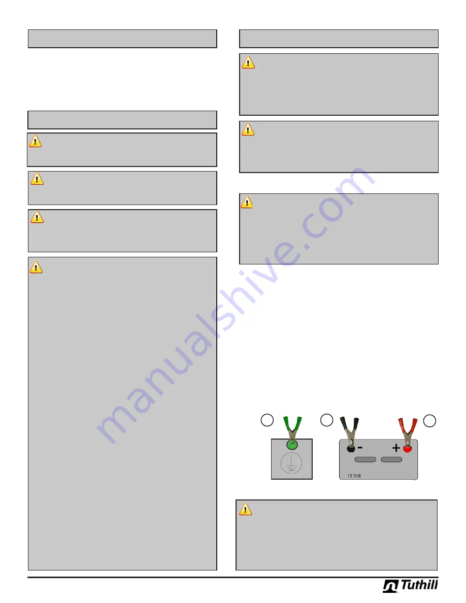
Inspect power cable before each use! Damage to the outer
jacket of the cable that exposes wiring requires replacement of
the power cable. The power cable terminates in black and red
clamps. Pumps with Explosion Proof motors also come with a
ground wire.
If so equipped,
the ground wire should be connected first.
Connect the ground wire to the vehicle chassis or earth
ground.
DO NOT
connect the ground wire to the negative
power source post.
Next, connect the black (negative) clamp to the negative
post of the DC power source.
Connect the red (positive) clamp to the positive post last.
1.
2.
3.
DC Power
Earth /
Chassis
Ground
1
2
3
AC Power
WARNING!
Electrical wiring should be performed ONLY
by a licensed electrician in compliance with local, state,
and national electrical code NEC/ANSI/NFPA 70, NFPA30,
and NFPA 30A, as appropriate to the intended use of the
pump.
The pump must be properly grounded.
Improper
installation or use of this pump can result in serious bodily
injury, or death!
Green
Black
Red
•
OPTIONS
•
825 or 850 digital meters, w/optional pulse output
•
2” NPT metallic or non-metallic inlet bung
•
Wrap around tubular mounting frame
•
UL listed Explosion Proof Motors
•
CE Certified Motors
•
Santoprene
®
or Hytrel
®
diaphragm


