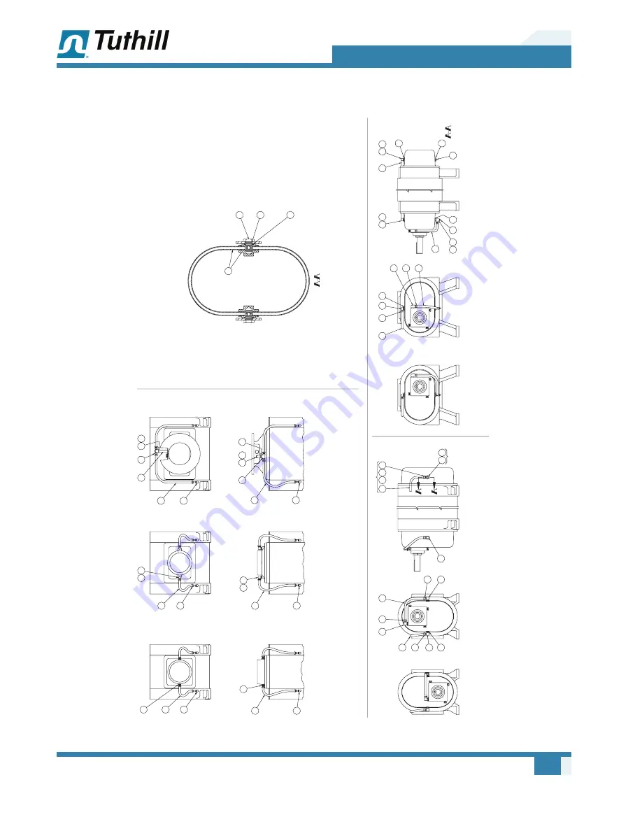
Tuthill M-D Pneumatics PD Plus Operating Manual Download Page 77

71

Assembly Drawings

Manual 2006 Rev B p/n 2006

Model 5500 – Double Envelope (Cooling Coil Option) – Side and End Views

VENTING DE

TA

IL

HORIZONT

AL

 FLOW

BOTT

OM DRIVE

TO

DRIVE

VERTICAL

 FLOW

HORIZONT

AL

 FLOW

NPT

5507

NPT

5507

NPT

551

1

FLANGED

5507, 551

1, 5514, & 5518

NPT

551

1

FLANGED

5507, 551

1, 5514, & 5518

VERTICAL

 FLOW

RIGHT DRIV

EL

EFT DRIVE

COOLING COIL

 DET

AIL

SCALE: 1/2

VENT 

TO

 INLET PORT

  RIGHT SIDE & 

TO

INLET SHOWN

(SEE F

ACT

OR

FOR FLOW DIRECTION

)

180

166

180

181

166

273

152

274

181

166

180

120

163

120

159

163

159

120
180

163

159

120

163

159

180

163

159

259

258

132

149

163

159

132

259

149
258

181

274

273

152

166

180

166

272

271

274

166
180

180

166

181

94

95

97

96

97

97

98

THIS SIDE

97

97

FARSIDE

97

SEC 

97

SEE SEC 
97

98

97

Summary of Contents for M-D Pneumatics PD Plus

Page 1: ...ht Double Envelope Gastight OPERATOR S MANUAL Tuthill Vacuum Blower Systems tuthillvacuumblower com 800 825 6937 WARNING Do Not Operate Before Reading Manual Operator s Manual Tuthill PD Plus Rotary Positive Displacement Blower Copyright 2017 Tuthill Vacuum Blower Systems All rights reserved Product information and specifications subject to change Manual 2006 Rev B p n 2006 ...

Page 2: ...inney vacuum pumps and M D PneumaticsTM blowers and vacuum boosters in Springfield Missouri USA We bring 100 years of engineering experience and solid hands on care to help customers keep their processes running Your satisfaction is important to us so please take time to provide your Tuthill sales representative with performance feedback We love to hear from our customers Tuthill is a family owned...

Page 3: ...onventions and Data Plate 2 Graphic Conventions in this Manual 2 Data Plate 3 Lifting 5 Description 6 Flow by Direction 7 Specifications 8 Installation 11 General 11 Location 13 Blower Air Intake 13 Soft Foot 14 Safety 14 Lubrication 15 Filling Procedure 16 Frequently Asked Questions Regarding Lubrication 17 ...

Page 4: ...ns and Specifications Cooling Coils Op tional 19 Motor Drives 19 Direct Coupled 19 V Belts 20 Setting V Belt Tension 20 Motor and Electrical Connections 22 Operation 23 General 23 Start Up Checklist 24 Operating 25 Methane Gas Applications 25 Water Injected Blowers 26 Operation 26 Shutdown 26 Recommended Shutdown Procedure to Minimize Risk of Freezing or Corrosion 27 Maintenance 28 General 28 Regu...

Page 5: ...embly 35 Adjusting Rotor Interlobe Clearance 35 Special Instructions Double Envelope 36 Drive Shaft Assembly 36 Troubleshooting 37 Assembly Clearances 39 Torque Chart 40 Recommended Lubricants 41 Recommended Lubricants for Rotary Blowers and Vacuum Boosters 41 Special Tool Drawings 43 Parts List 45 Assembly Drawings 54 Declaration of Incorporation 73 Warranty Blower Products 74 Operating Data Form...

Page 6: ...iv Table of Contents Manual 2006 Rev B p n 2006 ...

Page 7: ...properly installed and maintained will provide many years of reliable service Read and follow every step of these instructions when installing and maintaining the blower NOTE N Record the blower model and serial numbers of the machine in the OPERATING DATA form on the inside back cover of this manual Use this identification on any replacement part orders or if service or application assistance is ...

Page 8: ...hat if not avoided could result in death or serious injury CAUTION Indicates a hazardous situation that if not avoided could result in minor or moderate injury Indicates a situation that can cause damage to the engine personal property and or the environment or cause the equipment to operate improperly NOTE N Indicates a procedure practice or condition that should be followed in order for the equi...

Page 9: ...0 West Kearney Street Springfield Missouri USA 65803 YEAR MAWP MAX RPM Figure 2 1 General Operation and Symbols on Data Plate The following information is contained on the data plate WARNING Keep body clothing away from machine During operation keep body and clothing away from inlet and outlet of the blower WARNING Do not operate without guards in place CAUTION Hearing protection is required while...

Page 10: ...n 2006 MODEL NUMBER The specific model of the blower SERIAL NUMBER Unique to each blower YEAR Year of manufacture MAWP Maximum Allowable Working Pressure The standard MAWP is per Table 4 2 Maximum Operating Limits on page 9 The MAWP shall not be exceeded ...

Page 11: ...er must be handled using an appropriate device such as a fork truck or appropriate lifting device See Table 4 1 on page 8 for approximate weights Care should be taken to assure blower does not over turn during handling and installation LIFTING 03 ...

Page 12: ... discharge piping Compression occurs not internal to the blower but by the amount of restriction either downstream of the blower discharge port or upstream of the blower inlet port Figure 4 1 illustrates the air movement within the machine In addition the machine can operate in either direction Never attempt to control capacity by means of a throttle valve in the intake or discharge piping This wi...

Page 13: ...tion in inlet and discharge INTAKE INTAKE DISCHARGE INTAKE DISCHARGE HORIZONTAL FLOW VERTICAL FLOW DISCHARGE INTAKE DISCHARGE INTAKE DISCHARGE RIGHT DRIVE CW ROTATION LEFT DRIVE CW ROTATION LEFT DRIVE CCW ROTATION RIGHT DRIVE CCW ROTATION TOP DRIVE CW ROTATION TOP DRIVE CCW ROTATION BOTTOM DRIVE CW ROTATION BOTTOM DRIVE CCW ROTATION DISCHARGE INTAKE INTAKE INTAKE DISCHARGE DISCHARGE Figure 4 2 Flo...

Page 14: ...206 130 lb 59 kg 140 lb 64 kg 145 lb 66 kg 3210 165 lb 75 kg 175 lb 80 kg 180 lb 82 kg 4006 24 oz 0 71 L 24 oz 0 71 L 14 oz 0 42 L 14 oz 0 42 L 170 lb 77 kg 180 lb 82 kg 185 lb 84 kg 4009 200 lb 91 kg 210 lb 96 kg 215 lb 84 kg 4012 225 lb 182 kg 235 lb 107 kg 240 lb 109 kg 5507 57 oz 1 7 L 57 oz 1 7 L 32 oz 0 95 L 32 oz 0 95 L 400 lb 182 kg 415 lb 189 kg 420 lb 191 kg 5511 460 lb 209 kg 475 lb 216...

Page 15: ...i 1 035 mbar 15 inch Hg 508 mbar 280 F 156 C 4006 15 psi 1 035 mbar 15 inch Hg 508 mbar 300 F 167 C 4009 18 psi 1 241 mbar 17 inch Hg 575 mbar 360 F 200 C 4012 15 psi 1 035 mbar 15 inch Hg 508 mbar 300 F 167 C 5507 18 psi 1 241 mbar 17 inch Hg 575 mbar 360 F 200 C 5511 17 psi 1 172 mbar 17 inch Hg 575 mbar 360 F 200 C 5514 13 psi 896 mbar 15 inch Hg 508 mbar 300 F 167 C 5516 12 psi 827 mbar 15 inc...

Page 16: ...ithin certain approved limiting conditions The manufacturer s warranty is of course also contingent on such operation Maximum limits for pressure temperature and speed are specified in See Table 4 2 on page 9 for various blower sizes when operated under the standard atmospheric conditions Do not exceed any of these limits Specially ordered blowers with nonstandard construction or with rotor end cl...

Page 17: ... required Even with inlet and outlet silencers hearing protection will be required WARNING Customers are warned to provide adequate protection warning and safety equipment necessary to protect personnel against hazards in the installation and operation of this equipment in the system or facility WARNING The standard MAWP is per Table 4 2 The MAWP shall not be exceeded unless specific factory testi...

Page 18: ... using shims as necessary at bolting points to prevent warping the assembly Transmission of small operating vibrations to a support structure may be objectionable in some applications Use of vibration isolators or vibration absorbing materials can be effective in overcoming this transmission To avoid causing distortion apply the treatment under the common motor blower base or mounting plate rather...

Page 19: ...and kept as cool as possible because operating the blower at elevated temperatures can result in nuisance overload or temperature shutdowns An unprotected outdoor installation is satisfactory only when correct lubrication for the expected temperatures is provided See Recommended Lubricants on page 41 Blower Air Intake To minimize maintenance supply the blower with the cleanest air possible The air...

Page 20: ...t at 12 o clock position 5 Loosen the bolt on that foot Observe indicator travel and add shims as needed to reduce spring to less than 0 002 in 0 05 mm Repeat steps 4 and 5 on the remaining feet SAFETY Tuthill Vacuum Blower Systems recommends the use of relief valves to protect against excessive pressure or vacuum conditions Test these valves at initial start up to be sure they are properly adjust...

Page 21: ...efore operation Oil reservoirs are under the vacuum Shaft bearings at the gear end of the blower are splash lubricated by one or both gears dipping into an oil reservoir formed in the gear end plate and cover Shaft bearings at the drive end of the blower are lubricated by a slinger assembly dipping into an oil reservoir Before starting the blower fill the oil sumps as described in Filling Procedur...

Page 22: ... the fill until oil appears in the oil sight glass Bring the oil level to the center of the sight glass 3 Verify oil level is at proper level in both gear end and drive end sight glasses 4 Replace the fill plugs or breathers that were removed in step 1 HORIZONTAL FLOW VERTICAL FLOW END END SIDE SIDE MAGNETIC DRAIN PLUG 1 EA END PLATE MAGNETIC DRAIN PLUG 1 EA END PLATE OIL LEVEL GAUGE 1 EA END COVE...

Page 23: ...t This heat has to be dissipated through either surface contact with cooler materials or in a rest volume of lubricant While reducing the friction the lubricant is also going through a shearing process and the molecular structure is broken down The result is that the lubricant will begin to thicken because of the shorter molecular chains and the drop out of additive packages The thickened lubrican...

Page 24: ... piping Care should be taken when installing the blower to assure that there are no foreign objects or restrictions in the ports or piping COOLING COILS OPTIONAL CAUTION If the blower is to be located outdoors or in a building where the temperature surrounding the blower or the water supply and return piping can fall below 35 F 2 C then care must be taken to ensure that the water or other cooling ...

Page 25: ...ufacturer s instructions Blowers shipped with the motor directly coupled and mounted on a common base have been aligned prior to shipment Further alignment is not normally necessary but be sure to check the alignment and make adjustments if necessary prior to starting the blower Coupling halves must correctly fit the blower and drive shafts so that only light tapping is required to install each ha...

Page 26: ...mage A loose fit will result in shaft damage or breaking Make sure the motor sheave fits correctly and is properly aligned with the blower sheave Adjust the motor position on its sliding base so that belt tension is in accordance with drive manufacturer s instructions Always avoid excessive belt tension Recheck tension after the first 10 hours of operation and periodically thereafter to avoid slip...

Page 27: ...PROBLEM POSSIBLE CAUSES SOLUTION Belts slip sidewalls glazed Not enough tension Replace belts apply proper tension Drive squeals Shock load Apply proper tension Not enough arc of contact Increase center distance Heavy starting load Increase belt tension Belt s turned over Broken cord caused by prying on sheave Replace set of belts and install correctly Overloaded drive Redesign drive Impulse loads...

Page 28: ...tions It is the responsibility of the installer to assure that the motor is in compliance with the latest edition of IEC 60204 1 and all electrical connections are performed per IEC 60204 1 this includes overcurrent protection Wire the motor and other electrical devices such as solenoid valves and temperature switch to the proper voltage and amperage as indicated on the nameplate of the component ...

Page 29: ...rags or dirt have been left in blower 2 Be certain that inlet piping is free of debris If an open outdoor air intake is used be sure the opening is clean and protected by an inlet filter This also applies to indoor use 3 If installation is not recent check blower leveling drive alignment belt tension and tightness of all mounting bolts 4 Be certain the proper volume of oil is in the oil reservoir ...

Page 30: ...cedures be followed in sequence and checked off in the boxes provided in any of the following cases During initial installation After any shutdown period After maintenance work has been performed After blower has been moved to a new location DATES CHECKED Check the unit for proper lubrication Proper oil level is critical See Lubrication on page 15 See Recommended Lubricants on page 41 for informat...

Page 31: ... operation CAUTION Use of a thermowell insulates the thermocouple Invalid and delayed readings will result This can result in ineffective protection devices The upper temperature limits are not intended for continuous operation Consult with factory for detailed information assistance CAUTION Do not stop the blower if there are high outlet pressures in the outlet piping Unload the outlet piping pri...

Page 32: ...all fittings are tight 2 Check the water injection system to make sure water is available 3 Operate the blower dry for 3 minutes at no load to check for correct rotation and smooth operation 4 Turn the water on and adjust the flow as recommended for the individual blower Make sure the water discharges freely from the outlet piping 5 Apply vacuum and observe operation at the desired inlet condition...

Page 33: ...the risk of moisture condensation corrosion and freezing Care must be taken not to overload or overheat the blower during this procedure 1 Isolate the blower from the moist system piping allowing the blower to intake atmospheric air Operate the blower under a slight load allowing the blower to heat within safe limits The heat generated by the blower will quickly evaporate residual moisture 2 For c...

Page 34: ...routine maintenance inspect and assure that guards are in place and secure Pay special attention to lubrication of timing gears and bearings according to the information in Lubrication on page 15 When a blower is taken out of service it may require internal protection against rusting or corrosion The need for such protection must be a matter of judgment based on existing conditions as well as leng...

Page 35: ...l For major repairs not covered in this manual contact the nearest Tuthill Vacuum Blower Systems service representative When ordering parts supply the blower nameplate information as well as the item number and parts description as per the parts lists and assembly drawings Repair kits are available for all models These kits contain all the seals bearings O rings locks and special retaining screws ...

Page 36: ...drive shaft 5 Spray all exposed surfaces including the inlet and discharge flanges with rust preventative 6 Seal the inlet discharge and vent openings It is not recommended that the blower be set in place piped to the system and allowed to remain idle for a prolonged amount of time If any component is left open to the atmosphere the rust preventative will escape and lose its effectiveness 7 During...

Page 37: ... replacement is deemed necessary at any point of inspection appropriate instruction is given to achieve Remove the oil drain plugs in the bottom of the end covers and drain the oil Remove eight cap screws and remove the gear cover It may be necessary to tap the sides with a mallet or wooden block to break the seal joint Gears are not exposed for visual inspection prior to disassembly Broken teeth ...

Page 38: ...linger from the shaft on some models 16 Remove the flat head socket screw and washer from the opposite rotor 17 Use the bar pullers see Figure 8 4 and attach to free end plate bores Using the bar pullers pull the free end plate from rotor shafts NOTE N Using two bar pullers is recommended 18 Attach the bar puller to the gear end plate bore and push out the rotors one at a time 19 Using the rubber ...

Page 39: ...the seal shell as in step 2 Position the mechanical seal with the carbon face up and press the seal into each end plate bore Wipe the carbon with soft tissue and acetone or similar cleaner Make sure the seal is fully seated and the shell is not deformed Make sure the carbon is not scarred or cracked Mating rings will be seated later in the assembly procedure Gear End Assembly 4 Stand the rotors on...

Page 40: ...ng ring to be sure it is perfectly clean Use soft tissue and cleaning agent acetone if necessary Place a few drops of lubricating oil on its surface and install on the shaft with the lapped surface coming to rest on top of the carbon Gently press with fingers to make sure compression is taking place and the ring is not hung up for any reason 15 Lubricate the shafts and press the double row ball be...

Page 41: ...Lubricate the shafts and tap on the bearings 30 Install the oil retainer rings with button head screws 31 Install the oil slinger on lower rotor either shaft on vertical flow blowers spacer on the opposite shaft washers and screws Adjusting Rotor Interlobe Clearance 32 Lay the blower down with the drive gear on the left Using feeler gauges take interlobe readings and record on each side of housing...

Page 42: ... ring Be careful not to distort the snap ring B Install the second snap ring into the outer groove Place the mating ring from the first seal into the cover with the lap surface up Press the second mechanical seal in with the carbon side groove down until seated against outer snap ring The carbon will seal against the mating ring when the cover is installed on the drive shaft Drive Shaft Assembly A...

Page 43: ...ty oil See Lubrication on page 15 Excessive belt tension Check belt manufacturer s specifications for tension and adjust accordingly Coupling misalignment Check carefully Re align if necessary Lack of volume Slipping belts Check belt manufacturer s specifications for tension and adjust accordingly Worn lobe clearances Check for proper clearances See Assembly Clearances on page 39 Speed too low Inc...

Page 44: ...embly Clearances on page 39 Case or frame distortion Check mounting and pipe strain Excessive operating pressure Reduce pressure differential Excessive operating temperature Reduce pressure differential or reduce inlet temperature Vibration Belt or coupling misalignment Check carefully Re align if necessary Lobes rubbing Check cylinder for hot spots and then check for lobe contact at these points ...

Page 45: ... in 0 20 0 28 mm 4009 0 004 0 007 in 0 10 0 18 mm 0 008 0 012 in 0 20 0 30 mm 0 008 0 011 in 0 20 0 28 mm 4012 0 004 0 007 in 0 10 0 18 mm 0 010 0 014 in 0 25 0 36 mm 0 008 0 011 in 0 20 0 28 mm 4014 0 004 0 007 in 0 10 0 18 mm 0 012 0 016 in 0 30 0 41 mm 0 008 0 011 in 0 20 0 28 mm 5507 0 005 0 007 in 0 13 0 18 mm 0 009 0 013 in 0 23 0 33 mm 0 012 0 014 in 0 30 0 36 mm 5511 0 005 0 007 in 0 13 0 ...

Page 46: ...E CAP SCREW 10 32UNF 3 ft lb 4 N m CAP SCREW 1 4 20UNC GR5 6 ft lb 8 N m CAP SCREW 5 16 18UNC GR5 13 ft lb 17 N m CAP SCREW 3 8 16UNC GR5 23 ft lb 31 N m CAP SCREW 1 2 13UNC GR5 57 ft lb 77 N m CAP SCREW 5 8 14UNC GR5 113 ft lb 153 N m CAP SCREW 3 4 10UNC GR5 200 ft lb 271 N m TORQUE CHART 11 ...

Page 47: ... 32 F 18 to 0 C PneuLube ISO 100 SHC 626 ISO 68 MORLINA S4 B 68 ISO 68 32 to 90 F 0 to 32 C SHC 627 ISO 100 MORLINA S4 B 100 ISO 100 90 to 120 F 32 to 50 C SHC 629 ISO 150 MORLINA S4 B 150 ISO 150 RECOMMENDED MINERAL BASED FOOD GRADE LUBRICANTS AMBIENT TEMPERATURE LUBRICANT MEETING U S FDA REGULATION 21 CFR 178 3570 GOVERNING PETROLEUM PRODUCTS WHICH MAY HAVE INCIDENTAL CONTACT WITH FOOD AND USDA ...

Page 48: ...neral no additives or PAO synthetic oil RECOMMENDED GREASE FOR COMPETITOR PLUS BLOWERS TUTHILL CITGO Tuthill PneuLube NLGI 2 premium grade petroleum base lithium grease For food grade requirements Use Citgo Clarion Food Grade HTEP grease NLGI No 2 grade It meets all requirements of FDA Regulation 21 CFR 178 3570 the former USDA H 1 approval requirements for lubricants having incidental contact wit...

Page 49: ...OD 4 25 107 95 LONG TOOL ASSEMBLY FOR DRIVE SHAFT MECHANICAL SEAL INSTALLATION TOLERANCES XX 01 0 3 XXX 0005 0 05 CHAMFERS 2 Ø 1 38 REF 35 05 4 00 101 6 25 6 35 12 45 3 048 05 30 1 27 MIN R Ø 2 50 63 5 Ø 2 746 001 69 748 025 MATL P N CR1026T0 287075 4 25 107 95 LG MATL COLD ROLLED 1026 TUBE 2 875 73 025 OD 4 25 107 95 LONG TOOL ASSEMBLY FOR DRIVE SHAFT MECHANICAL SEAL INSTALLATION TOLERANCES XX 01...

Page 50: ...NG TOLERANCES FRACTIONAL CHAMFERS 0005 0 0127 2 75 19 02 2 REF 50 8 0 44 REF 11 17 R 0 22 5 58 TYP 1 25 4 0 5 12 7 5 25 133 35 2 63 66 80 1 25 4 SNAP ON P N CJ66 16 3 OR EQUIVALENT SNAP ON P N CJ83 3 OR EQUIVALENT Ø 0 69 17 52 3 4 16UNF 2B Figure 13 5 4000 5500 Gear and EP Tool T29603 NOTE N All dimensions are shown in inches and millimeters ...

Page 51: ...2 27 Lock Washer 24 28 Gasket 2 29 Cap Screw 4 30 Cap Screw 16 31 Magnetic Pipe Plug 2 37 Breather 2 38 Port Fitting 2 39 Port Fitting Gasket 2 40 Cap Screw 24 ITEM NO PART DESCRIPTION QTY 41 Lock Washer 24 42 Nameplate 1 45 Drive Shaft 1 47 Retaining Ring 1 50 Bearing 1 51 Lab Seal 4 57 Spacer 1 66 Cap Screw 2 67 Spacer 2 70 Oil Gauge 2 85 Pipe Plug 6 98 Pipe Plug 6 121 Pipe Plug 3 123 Bearing Sp...

Page 52: ... Lock Washer 24 28 Gasket 2 29 Cap Screw 4 30 Cap Screw 16 31 Magnetic Pipe Plug 2 37 Breather 2 38 Port Fitting 2 40 Cap Screw 24 41 Lock Washer 24 42 Nameplate 1 45 Drive Shaft 1 ITEM NO PART DESCRIPTION QTY 47 Retaining Ring 1 50 Bearing 1 51 Lab Seal 4 54 Mechanical Seal 4 57 Spacer 1 66 Cap Screw 2 67 Spacer 2 70 Oil Gauge 0 85 Pipe Plug 6 98 Pipe Plug 10 121 Pipe Plug 2 123 Bearing Spacer 2 ...

Page 53: ...8 Port Fitting 2 40 Cap Screw 24 41 Lock Washer 24 42 Nameplate 1 45 Drive Shaft 1 50 Bearing 1 51 Lab Seal 4 54 Mechanical Seal 4 ITEM NO PART DESCRIPTION QTY 57 Spacer 1 66 Cap Screw 2 67 Spacer 2 70 Oil Gauge 0 74 Spacer 1 75 O Ring 1 76 Mechanical Seal 1 77 Spacer 1 82 Washer 1 83 Lock Nut 1 85 Pipe Plug 6 91 Drive Shaft Seal Adapter 1 92 O Ring 1 93 Cap Screw 4 98 Pipe Plug 10 118 Shim 1 118 ...

Page 54: ...35 Lock Nut 2 36 Washer 2 37 Breather 2 38 Port Fitting 2 39 Port Fitting Gasket 2 40 Cap Screw 28 41 Lock Washer 28 42 Nameplate 1 45 Drive Shaft 1 47 Retaining Ring 1 50 Bearing 1 ITEM NO PART DESCRIPTION QTY 51 Lab Seal 4 61 Bearing Lock Plate 4 62 Cap Screw 8 65 Lock Plate 2 66 Cap Screw 4 68 Dowel Pin 1 69 Cap Screw 1 70 Oil Gauge 2 85 Pipe Plug 4 6 98 Pipe Plug 4 121 Pipe Plug 6 2 123 Bearin...

Page 55: ...35 Lock Nut 2 36 Washer 2 37 Breather 2 38 Port Fitting 2 40 Cap Screw 28 41 Lock Washer 28 42 Nameplate 1 45 Drive Shaft 1 47 Retaining Ring 1 50 Bearing 1 51 Lab Seal 4 54 Mechanical Seal 4 ITEM NO PART DESCRIPTION QTY 61 Bearing Lock Plate 4 62 Cap Screw 8 65 Lock Plate 2 66 Cap Screw 4 68 Dowel Pin 1 69 Cap Screw 1 70 Oil Gauge 2 6 85 Pipe Plug 4 8 98 Pipe Plug 8 2 121 Pipe Plug 6 2 123 Bearin...

Page 56: ... Mechanical Seal 4 61 Bearing Lock Plate 8 62 Cap Screw 2 65 Lock Plate 4 66 Cap Screw 1 68 Dowel Pin 1 69 Cap Screw 1 70 OIl Gauge 2 ITEM NO PART DESCRIPTION QTY 74 Spacer 2 75 O Ring Viton 2 76 Mechanical Seal 1 77 Drive Shaft Face Seal Sleeve 2 78 Retaining Ring 2 82 Washer 1 83 Lock Nut 1 85 Pipe Plug 7 8 86 Shim 1 87 Sleeve 1 88 O Ring Viton 1 89 Spacer 1 90 Set Screw 2 91 Drive Shaft Adapter...

Page 57: ... 2 37 Breather 2 38 Port Fitting 2 39 Port Fitting Gasket 2 40 Cap Screw 28 42 Nameplate 1 45 Drive Shaft 1 46 Ring Adapter 1 47 Retaining Ring 1 50 Bearing 1 51 Lab Seal 4 ITEM NO PART DESCRIPTION QTY 57 Bearing Spacer 1 61 Bearing Lock Plate 6 62 Cap Screw 12 65 Lock Plate 2 66 Cap Screw 4 68 Dowel Pin 1 69 Cap Screw 1 70 Oil Gauge 2 85 Pipe Plug 6 4 98 Pipe Plug 4 121 Pipe Plug 2 123 Bearing Sp...

Page 58: ...2 36 Washer 2 37 Breather 2 38 Port Fitting 2 40 Cap Screw 28 42 Nameplate 1 45 Drive Shaft 1 46 Adapter Ring 1 47 Retaining Ring 1 50 Bearing 1 51 Lab Seal 4 54 Mechanical Seal 4 57 Bearing Spacer 1 ITEM NO PART DESCRIPTION QTY 61 Bearing Lock Plate 6 62 Cap Screw 12 65 Lock Plate 2 66 Cap Screw 4 68 Dowel Pin 1 69 Cap Screw 1 70 Oil Gauge 2 85 Pipe Plug 10 8 98 Pipe Plug 4 123 Bearing Spacer 2 1...

Page 59: ...earing Spacer 1 61 Bearing Lock Plate 6 62 Cap Screw 2 65 Lock Plate 4 66 Cap Screw 1 68 Dowel Pin 1 69 Cap Screw 1 ITEM NO PART DESCRIPTION QTY 70 Oil Gauge 2 74 Spacer 2 75 O Ring Viton 2 77 Drive Shaft Face Seal Sleeve 2 80 Washer 1 82 Washer 1 83 Lock Nut 1 85 Pipe Plug 7 8 86 Shim 1 86 Shim 4 91 Drive Shaft Adapter Seal 1 92 O Ring Viton 1 93 Cap Screw 4 98 Pipe Plug 8 123 Bearing Spacer 2 13...

Page 60: ...54 Assembly Drawings Manual 2006 Rev B p n 2006 ASSEMBLY DRAWINGS Model 3200 Standard Seals Cutaway View ...

Page 61: ...55 Assembly Drawings Manual 2006 Rev B p n 2006 Model 3200 Standard Seals Side and End Views ...

Page 62: ...43 241 244 245 123 26B 54 57 81 84 SERIES 16 47 13 003 TO 009 BEYOND ITEM 91 SEE ITEM 118 64 67 SERIES NOT TO SCALE VIEW 91 REF 6 25 8 29 24 18 30 20 14 9 51 22 INSERT REQD NO OF SHIMS TO ACHEIVE DIMENSION SHOWN IN VIEW A 45 23 83 91 82 64 67 SERIES 92 77 76 75 74 NOTE 64 67 SERIES BEARING ARE SHIELDED INSTALL WITH SHIELD TOWARD MECHANICAL SEAL 66 49 16 50 27 17 25 1 EA END COVER 54 57 81 84 SERIE...

Page 63: ... B p n 2006 Model 4000 Standard Seal Cutaway Views OIL LEVEL SIGHT GAUGE DETAIL 241 244 234 242 243 24 8 6 36 35 129 22 51 12 245 45 13 47 23 50 66 65 62 15 61 14 9 1 1 EA END COVER 28 22 129 12 51 123 7 21 69 3 4 27 26 30 68 10 25 29 15 ...

Page 64: ...58 Assembly Drawings Manual 2006 Rev B p n 2006 Model 4000 Lip Labyrinth Side and End Views ...

Page 65: ...B p n 2006 Model 4000 Single Envelope Cutaway View O RING BETWEEN END PLATE HOUSING BOTH END PLATES O RING OPTION 35 36 24 6 8 28 22 9 22 62 45 47 13 23 50 66 65 26 27 14 61 15 1 54 51 28 4 22 176 3 7 21 69 3 4 25 10 68 29 27 26 123 15 30 ...

Page 66: ...TING DETAIL OIL LEVEL SIGHT GAUGE DETAIL 121 174 121 234 245 244 242 241 243 121 121 121 174 174 1 EA END PLATE 1 EA END PLATE 1 EA END PLATE 38 2 EA PORT 85 31 41 40 37 2 EA END PLATE 98 OIL LEVEL SIGHT GAUGE 1 EA END PLATE SEE DETAIL 1 EA END PLATE 31 38 40 41 37 2 EA PORT 85 70 1 EA END PLATE 4 EA END PLATE 98 4009 1 EA PORT 85 1 EA PORT 4012 2 EA PORT 85 1 EA PORT FARSIDE 98 2 EA END PLATE 37 ...

Page 67: ...ngle Envelope Cooling Coil Option Side and End Views HORIZONTAL FLOW VERTICAL FLOW COOLING COIL OPTION 180 166 180 166 181 180 166 181 180 181 166 181 97 97 97 98 97 98 FARSIDE 97 97 98 96 COOLING COIL DETAIL TYP BOTH ENDS SCALE NONE SEC 95 98 SEE SEC 97 97 94 97 ...

Page 68: ... BETWEEN END PLATE HOUSING BOTH END PLATES 35 36 24 000 TO 005 BELOW ITEM 91 INSERT SHIMS IF REQD BETWEEN SLEEVE ITEM 87 BEARING ITEM 50 TO ACHIEVE DIMENSION SHOWN ABOVE 92 82 86 6 9 22 8 22 88 75 140 23 91 45 87 83 89 90 76 77 93 74 50 66 65 61 62 14 15 51 4 22 176 3 54 7 21 69 4 1 3 25 68 10 29 15 26 30 123 ...

Page 69: ...000 64 4009 SHOWN 1 EA END PLATE 31 2 EA PORT 38 85 4 EA END PLATE 98 LEFT DRIVE RIGHT DRIVE 2 EA END PLATE 98 85 OIL LEVEL SIGHT GAUGE 1 EA END PLATE SEE DETAIL 1 EA END PLATE 31 4009 SHOWN 4000 67 38 85 40 OPTIONAL FLANGED PORT FITTING DETAIL 1 EA END PLATE 70 121 1 EA END PLATE 4009 1 EA PORT 85 1 EA PORT 4012 2 EA PORT 85 1 EA PORT OIL LEVEL SIGHT GAUGE DETAIL 2 EA END PLATE 2 EA PORT 121 FARS...

Page 70: ... Views VERTICAL FLOW TOP DRIVE BOTTOM DRIVE LEFT DRIVE RIGHT DRIVE COOLING COIL OPTION COOLING COIL DETAIL 180 166 181 166 180 273 152 274 181 180 166 166 271 272 274 273 152 166 181 97 180 180 166 181 HORIZONTAL FLOW 97 97 97 97 96 97 98 FARSIDE TYP BOTH ENDS SCALE NONE SEC 95 98 97 SEE SEC 97 94 97 ...

Page 71: ...B p n 2006 Model 5500 Standard Seal Cutaway View OIL LEVEL SIGHT GAUGE DETAIL 5511 MODEL SHOWN 242 245 243 241 234 244 123 129 129 35 61 36 24 62 12 22 3 50 46 45 13 23 47 6 66 65 8 14 4 9 51 51 12 30 21 7 1 4 26 28 27 14 10 69 68 57 29 25 ...

Page 72: ...06 Model 5500 Single Envelope Cutaway View TYP FOR BOTH END PLATES SCALE 1 2 O RING SEALING ARRANGEMENT OPTION R 5514 SHOWN 126 123 176 22 36 35 8 6 62 61 4 22 22 24 24 45 47 46 23 13 50 14 66 65 4 9 3 1 28 21 7 30 69 51 54 68 57 29 25 10 14 27 26 ...

Page 73: ...241 242 245 243 244 234 174 174 174 2 EA END PLATE 2 EA END PLATE 98 1 EA END PLATE 31 85 SEE PORT DETAIL 38 37 27 40 1 EA END PLATE 85 1 EA END PLATE 1 EA END PLATE 31 SEE PORT DETAIL 27 40 38 1 EA END PLATE 2 EA END PLATE 85 OIL LEVEL SIGHT GAUGE 1 EA END COVER SEE DETAIL 1 EA END PLATE 2 EA PORT 85 37 OIL LEVEL SIGHT GAUGE 1 EA END PLATE SEE DETAIL 85 37 FARSIDE 2 EA PORT 85 38 85 85 85 1 EA EN...

Page 74: ...507 5511 5514 5518 HORIZONTAL FLOW BOTTOM DRIVE TOP DRIVE VERTICAL FLOW RIGHT DRIVE LEFT DRIVE COOLING COIL DETAIL SCALE 1 2 VENT TO INLET PORT RIGHT SIDE TOP INLET SHOWN SEE FACTORY FOR FLOW DIRECTION 180 166 181 181 166 180 120 163 120 159 163 159 120 180 163 159 120 163 159 180 163 159 259 258 132 149 163 159 132 259 149 258 181 166 180 166 180 180 166 181 97 97 98 THIS SIDE 97 97 FARSIDE 97 SE...

Page 75: ... DRIVE SHAFT MECHANICAL SEAL ASSEMBLY DETAIL SCALE FULL 140 255 224 225 136 123 126 176 51 INSERT SHIMS IF REQD BETWEEN SPACER ITEM 74 AND DRIVE SHAFT BEARING TO ACHIEVE DIMENSION SHOWN 82 000 TO 005 BELOW ITEM 91 92 50 74 86 75 83 45 91 77 93 54 35 36 20 40 24 62 61 22 45 64 64W SERIES TOP DRIVE ONLY 80 23 91 93 6 66 65 8 14 4 9 4 22 21 30 69 68 1 3 54 57 29 10 25 26 14 7 ...

Page 76: ...34 241 242 245 243 244 174 174 174 174 174 2 EA END PLATE 2 EA END PLATE 98 85 1 EA END PLATE 31 85 SEE PORT DETAIL 38 40 85 1 EA END PLATE 1 EA END PLATE 31 1 EA END PLATE 85 SEE PORT DETAIL 40 38 85 1 EA END PLATE 2 EA END PLATE OIL LEVEL SIGHT GAUGE 1 EA END COVER SEE DETAIL 1 EA END PLATE 85 2 EA PORT 38 OIL LEVEL SIGHT GAUGE 1 EA END PLATE SEE DETAIL 85 FARSIDE 85 2 EA PORT 85 38 85 85 1 EA E...

Page 77: ... 5511 FLANGED 5507 5511 5514 5518 VERTICAL FLOW RIGHT DRIVE LEFT DRIVE COOLING COIL DETAIL SCALE 1 2 VENT TO INLET PORT RIGHT SIDE TOP INLET SHOWN SEE FACTORY FOR FLOW DIRECTION 180 166 180 181 166 273 152 274 181 166 180 120 163 120 159 163 159 120 180 163 159 120 163 159 180 163 159 259 258 132 149 163 159 132 259 149 258 181 274 273 152 166 180 166 272 271 274 166 180 180 166 181 94 95 97 96 97...

Page 78: ...72 Assembly Drawings Manual 2006 Rev B p n 2006 ...

Page 79: ...d has been declared in conformity with the provisions of the relevant directive s Other directives and standards that apply to this Declaration of Incorporation EN 1012 1 1996 Compressors and vacuum pumps Safety requirements Part 1 Compressors The scope of the Declaration of Incorporation is for bare shaft Rotary Positive Displacement PD Plus Blowers Models 3200 4000 5500 Lip Labyrinth Air Service...

Page 80: ...y Seller Unless done with prior written consent of Seller any repairs alterations or disassembly of Seller s equipment shall void warranty Installation and transportation costs are not included and defective items must be held for Seller s inspection and returned to Seller s Ex works point upon request THEREARE NO WARRANTIES EXPRESSED IMPLIED OR STATUTORY WHICH EXTEND BEYOND THE DESCRIPTION ON THE...

Page 81: ...ze Length Serial No Type of Lubrication Start up Date Pump RPM Operating Vacuum Pump Sheave Diameter Any Other Special Accessories Supplied or in Use Motor Sheave Diameter Motor RPM HP NOTES IMPORTANT All blowers manufactured by Tuthill Vacuum Blower Systems are date coded at time of shipment In order to assure you of the full benefits of the product warranty please complete tear out and return th...

Page 82: ...0 825 6937 F 417 865 2950 tuthillvacuumblower com Technical Support 1 877 955 TECH 8324 Service Repair or Product Sales I N T ERNATIONAL QUALITY STAND A R D REGISTERED VACUUM BLOWER SYSTEMS TUTHILL CORPORATION Copyright 2017 Tuthill Vacuum Blower Systems All rights reserved Product information and specifications subject to change 1 18 ...

Reviews: