Tuthill 4000 Series Installation And Service Instructions Manual Download Page 4

Page 4 of 18

The Pumping Principle

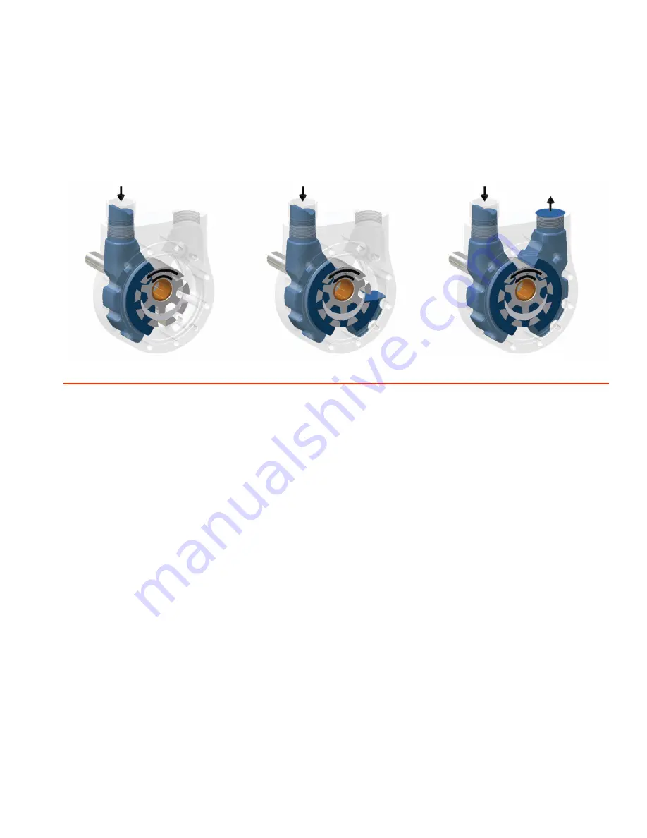
Tuthill 4000 Series cast iron pumps employ the internal gear pumping principle. There are only two moving parts. Pumping action is 

based on a rotor, idler gear, and crescentshaped partition cast integral with the cover. Power applied to the rotor is transmitted to the 

idler gear with which it meshes. The space between the outside diameter of the idler and the inside diameter of the rotor is sealed by 

the crescent. As the pump starts, the teeth come out of mesh, increasing the volume. This creates partial vacuum, drawing the liquid 

into the pump through the suction port. The liquid fills the spaces between the teeth of the idler and the rotor and is carried past the 

crescent partition through the pressure side of the pump. When the teeth mesh on the pressure side, the liquid is forced from the 

spaces and out through the discharge port.

WARNING

Failure to follow these instructions could result in serious bodily injury or death. These pumps should not be used for handling plain 

water, corrosive or abrasive liquids or liquids not possessing adequate lubricity. Do not attempt to work on any Tuthill pump installation 

before completing the steps below. Disconnect the drive so that it cannot be started while work is being performed. Review the Material 

Safety Data Sheet (MSDS) applicable to the liquid being pumped to determine its characteristics and the precautions necessary to 

ensure safe handling. Vent all pressure within the pump through the suction or discharge lines. All Tuthill pumps contain residual 200 

SSU lube oil from the factory production test. Determine if this is compatible with the fluid you are pumping. If the fluid is incompatible, 

consult the factory. If the pump is to be operated at elevated temperatures, the pump should be brought up to operating temperatures 

gradually. Rapid or sudden introduction of liquids at elevated temperatures into the cold liquid chamber of the pump could cause 

damage to pump externals, seals or other internal parts. Do not run the pump dry. Failure to comply with this could cause severe 

damage to the internal seal, bushings and/or metal parts. Pump needs to be Earthed separately to avoid build up of Electro-Static 

Charge.

Tuthill 4000 Series pumps are required to develop 25” mercury vacuum at 0 psi on factory test. While these pumps will develop as 

high as 27” of vacuum, it is a sound engineering practice to avoid extreme vacuum whenever possible. Select a pipe size to reduce line 

friction loss to a minimum.

The pump should be located as close to the source of supply as conditions permit and if possible, below the level of the liquid in the 

reservoir. When necessary to locate the pump in a pit, provisions should be made to safeguard against flooding. Care must be taken to 

properly support the suction and discharge piping so that no strain is put on the pump due to either weight or expansion. Piping strain 

can result in misalignment, hot bearings, worn couplings, and vibration. It is important that the piping used be clean and free of chips 

and scales.

Summary of Contents for 4000 Series

Page 1: ...Installation and Service Instructions Excellenceatwork Excellenceinlife 4000 Series Pumps ...

Page 2: ...ump Disassembly 10 Inspection 10 Pump Assembly 10 Changing Rotation 10 4312 4316 Parts List 11 Seal Replacement 11 4332 4336 Parts List 12 Seal Replacement and Resetting of Clearances 13 Pump Disassembly 14 Inspection 14 Pump Assembly 14 Changing Suction Ports While Maintaining Shaft Rotation 14 Changing Shaft Rotation While Maintaining Suction Ports 15 Changing Suction Ports While Changing Shaft ...

Page 3: ...ential pressure to 500 PSI 34 bar and have a maximum discharge pressure of 500 PSI 17 bar Differential and maximum pressure is limited to 300 PSI 20 bar in model 4108 These pumps are self priming and particularly suited to handle liquids of 35 to 1000 SSU 2 to 200 centipoise Higher viscosities can be handled at reduced speeds A mounting foot is available as an option as is an internal relief valve...

Page 4: ... safe handling Vent all pressure within the pump through the suction or discharge lines All Tuthill pumps contain residual 200 SSU lube oil from the factory production test Determine if this is compatible with the fluid you are pumping If the fluid is incompatible consult the factory If the pump is to be operated at elevated temperatures the pump should be brought up to operating temperatures grad...

Page 5: ...d be filled with oil at installation and should never be allowed to run dry Every pump installation should have a good foundation Its structure should be sufficiently strong to hold the pump rigid and to absorb any strain or shock that may be encountered The installation should be leveled checked for proper piping alignment and then fastened securely Method of Drive Direct drive through a traditio...

Page 6: ... relief valve setting should be reset in the actual operating condition To adjust the relief setting within the range of a given spring s capability Remove the acorn nut Not supplied with models 4108 Insert a screwdriver into the slot of the adjusting screw and hold it steady Loosen the locking nut with a wrench by turning counterclockwise Throttle the outlet line until the differential pressure a...

Page 7: ...evere damage to the seal bushing and or metal parts Startup Prior to starting the pump double check the following Pressure and vacuum gauges should be installed as close as possible to the pump Rotate pump shaft to ensure it turns freely without binding Recheck alignment and ensure all guards are in place Make sure piping is independently supported and no strain is being transmitted to the pump Ma...

Page 8: ... List 1 2 3 4 5 6 7 8 9 10 11 Item Description Item Description 1 Housing 7 Retaining Ring 2 Cover Assembly 8 Mechanical Seal 3 Idler Gear 9 O Ring 4 Cover Screws 10 Housing Plug 5 Cover Gasket 11 Rotor 6 Housing Bushing Models 4101 4121 4102 4122 4103 4123 4104 4124 only ...

Page 9: ...t and or keyway place seal assembly on the pump shaft Push seal down with your fingers to a position approximately half way down the shaft For modification A tang shafts use a tapered plastic sleeve available from Tuthill part 1LPF531 7010 Lubricate the sleeve and place seal assembly on the sleeve The tapered end of the sleeve fits into the spring end of the seal assembly Place the slotted end of ...

Page 10: ...quire replacement of the housing bracket rotor or all three parts Pump Assembly Clean all parts thoroughly using great care to eliminate all dirt Install the rotor in the pump housing Apply the gasket to the cover Use a new gasket if the old one is damaged Models 4101 4121 and 4108 4128 are also supplied with an o ring between the cover and housing Replace if damaged Place the idler gear on the pi...

Page 11: ...the shaft Use a small fine file if needed Remove the seal gland cap screws Slide the seal gland cap off the shaft Remove the stationary seat of the seal from the seal gland Slide the seal cartridge off the shaft Polish the pump shaft with crocus cloth or very fine sandpaper and clean the seal chamber thoroughly with a clean cloth This will prevent damage to the new seal and ease installation Place...

Page 12: ...Description Item Description 1 Cover 11 Retaining Ring 2 Housing 12 Thrust Washer 3 Bracket 13 Thrust Bearing 4 Idler Gear 14 Lip Seal 5 Seal Gland 15 Set Screw 6 Adjusting Sleeve 16 Cover Screws 7 Rotor 17 Nut 8 O Ring 18 Cover Screws 9 O Ring 19 Lockwasher 10 Mechanical Seal 20 Gland Screws ...

Page 13: ...ngers to a position approximately half way down the shaft 14 Press the new stationary seat into the housing plug Make sure the lapped surface is facing up Protect the lapped surface by covering it with a piece of paper when pressing down on the face Use your fingers for this operation The stationary seat must be seated squarely in the housing plug 15 Place a new o ring on the OD of the housing if ...

Page 14: ... dirt Install the rotor in the pump bracket Install the housing over the rotor head positioned on the bracket register Place the idler gear on the pin in the cover assembly and position in the housing register Align the matching marks for proper location Install the cover screws Tighten gradually alternating from a screw on one side to a screw on the opposite side Install the seal following the in...

Page 15: ... following Looking at the pump from the shaft end with the ports up note the location of the V notch in the bracket If at the top 12 o clock rotation is clockwise If at the bottom 6 o clock counterclockwise Remove the cover screws so that the cover moves freely Rotate the cover 180 Align the mounting holes and reinstall the cover screws making sure the seal gland is vented to the suction side of t...

Page 16: ...ide of the pump If outfitted with an internal relief valve the rotation cannot be changed in the field unless the cover valve assembly is also replaced WARNING Failure to follow these instructions could result in serious bodily injury or death Do not attempt to work on any Tuthill pump installation before completing the steps below Disconnect the drive so that it cannot be started while work is be...

Page 17: ...uld never exceed 15 of mercury Vaporization caused by higher vacuums will generally result in capacity drop off Suction conditions must be redesigned Pump speed is too slow The strainer is too small or obstructed The suction port or pipe is not immersed deeply enough in the liquid Piping is improperly installed permitting an air pocket to form in the pump Pump works spasmodically Leaky suction lin...

Page 18: ...ll Pump Group warrants its products against defective material and workmanship for 90 days from the date of startup or one year from date of shipment from Tuthill s plant whichever comes first This warranty does not include products damaged by tampering improper installation abuse or wear Nor does it cover consequential damages or other losses due to pump failure Because of the unpredictable natur...

Reviews: