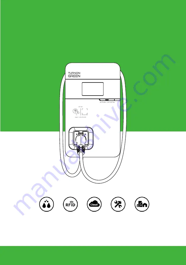
Electric Vehicle AC Charger
EVP1100 Series - User Manual
Copyright © 2021. TurnOnGreen Technologies, a subsidary of TurnOnGreen, Inc. All Rights Reserved.
Outdoors
NEMA 4 Authorization
Management Repairable
Page 1: ...Electric Vehicle AC Charger EVP1100 Series User Manual Copyright 2021 TurnOnGreen Technologies a subsidary of TurnOnGreen Inc All Rights Reserved Outdoors NEMA 4 Authorization Management Repairable...
Page 2: ......
Page 3: ...14 9 1 Safety Requirements 14 9 2 Power Grid Connection and Grounding Type 15 9 3 Packing List 17 9 4 Tools and Materials Required 18 9 5 Wall Mount Bracket Installation Requirements 18 9 6 EVP1100 I...
Page 4: ...chemicals or vapors Turn off the input power of the charger before performing any maintenance on the charger The device is designed only for vehicles that are compatible with the SAE J1772 Level 2 cha...
Page 5: ...er the vehicle s battery and the charger This type is damage is not covered by our warranty policy Ensure that the charging cable is well positioned during the charging process to avoid the cable gett...
Page 6: ...rence to radio communications However there is no guarantee that interference will not occur in a particular installation If this equipment does cause harmful interference to radio or television recep...
Page 7: ...ntenna or transmitter Radiation Exposure Statement This equipment complies with FCC radiation exposure limits set forth for an uncontrolled environment This equipment should be installed and operated...
Page 8: ...ater than 20cm between the radiator your body D claration d exposition aux radiations Cet quipement est conforme aux limites d exposition aux rayonnements ISED tablies pour un environnement non contr...
Page 9: ...nada authorization is no longer considered valid and the IC ID can not be used on the final product In these circumstances the OEM integrator will be responsible for re evaluating the end product incl...
Page 10: ...4 Interface 4 1 Surface 5 LCD Screen SAE J1772 AC Charging Connector Wall Mount Bracket with Power Box AC Power Inlet Charging Cable Inlet LED Light Indication 7 EVP1100 Series User Manual...
Page 11: ...se and Wire box Ethernet Inlet Blade Female Connector Ethernet Inlet Hole Network and setting Port Power and Grounding Setting Blade Male connector For 4G SIM Card AC Inlet AC Inlet Hole 8 POWERING PO...
Page 12: ...5 1 Main Size of Charger 5 2 Wall Mount Bracket 5 Dimensions unit mm 295 158 505 264 7 384 2 42 163 8 197 8 257 8 337 8 369 7 0 0 50 40 50 87 9 EVP1100 Series User Manual...
Page 13: ...idity Up to 85 at 50 C non condensing Relative Storage Humidity Up to 95 at 50 C non condensing Display LED pilot lamp standard 5 inch LCD High end User Authorization RFID ISO IEC 14443A B ISO IEC 156...
Page 14: ...ht Idle Backend disconnected Sleep Breathing Yellow Idle Backend disconnected Constantly Bright Yellow Authorize RFID authorization Pass Flicker 3 sec Authorize RFID authorization Fail Flicker 3 sec H...
Page 15: ...ult 012200 System input OVP 012203 System input UVP 012212 System input drop 012216 System output OCP 012223 System ambient inlet OTP 012233 RCD CCID trip Status Code 4G connected with internet 4G Not...
Page 16: ...n failed 012256 Ground Fault 012257 MCU self test Fault 012262 Syetem output Circuit Short 012344 Meter IC communication timeout 012345 Pilot negative error 013607 CSU mrware update fail 013622 Discon...
Page 17: ...witch for each ungrounded conductor of AC input shall be provided by others in accordance with the National Electric Code ANSI NFPA 70 Verify that the Wall Connector is properly grounded The ground co...
Page 18: ...Type Switch 1 Power Grid Type Switch 2 Grounding System ON LN IT OFF LL TT TN 120V 120V 208V PE L1 L2 V 2 V 2 V PE L1 L2 0 V V PE L N V 240 or 200 volt Charger input terminal Charger input terminal C...
Page 19: ...make sure the input power is turned OFF Use a non conductive object to set the rotary switch Switch Setting Number 8 9 A B 1 C D E F Maximum Output Current 30A 32A 40A 48A Invalid Setting Invalid Set...
Page 20: ...ench 1 9 M5 Screw 5 Product Certification Date of inspection Inspector 1 2 3 4 5 6 7 8 9 R F I D Classic Edition Electric Vehicle AC Charger AX Series User Manual COPYRIGHT 2021 reserves the right to...
Page 21: ...AWG wire and fixed by M5 slotted head screw It is recommended to use 1 inch liquidtight flexible metal conduit compliant with NEMA 4 class Slotted head screwdriver for M5 9 4 Tools and Materials Requi...
Page 22: ...es to loop around the wires and to allow related maintenance If in an enclosed garage on the side of vehicle charging inlet 9 6 EVP1100 Installation Requirements Warning for Wi Fi and 4G versions Due...
Page 23: ...ate and locate all the installation holes Use as a template to mark on the wall with a pencil or any tool and insert 4 sets of expansion bolts M5X40mm into the wall as shown in the figure Install the...
Page 24: ...the AC power cord The cross sectional area of the three power cords should be AWG 6 or 14mm2 The power cords should be fully crimped and connected with ring terminals The ring terminals should be atta...
Page 25: ...cable entrance Once the network cable is in insert the RJ45 connector into the connection port on the back of the charger STEP 4 STEP 5 Setting of the power supply type and grounding type There are di...
Page 26: ...SIM card password has been removed prior to installation as the charger post does not support SIM cards with passwords Installation of the charger First connect the network cable to the charger NOTE...
Page 27: ...nductive spring plate of the wire box Meanwhile apply pressure to the equipment so that the three screw holes of the equipment align with the three holes of the wall mounted metal plate Finally tighte...
Page 28: ...0 4 Charger Standard Setting instructions Power off and unplug the connection Power off the machine and remove the network cable once setting is completed For those who are in a wired network environm...
Page 29: ...on the charger in the order bottom right left Pull the network cable out of the wire box then remove the network cable Install the waterproof plug then re install the charger and wire box 1 2 3 26 PO...
Page 30: ...oles of the equipment align with the three holes of the wall mounted metal plate then tighten with the M6 plum screws in the order left right bottom with a tightening torque of 30 kg cm 1 2 3 27 EVP11...
Page 31: ...out two turns so that the charging gun wire will not hang down to the ground Once the wrapping is done insert the charging gun head into the hole of the charging gun base on the front panel of the mac...
Page 32: ...environment may influence the time server connection STEP1 Connect the RJ45 cable to the charger Connect the RJ45 cable to the notebook Use the following IP address IP address 192 168 1 1 Subnet mask...
Page 33: ...he Networking Edition restart the charger For Wi Fi and 4G versions continue to step 10 2 or 10 3 to complete the settings process 192 168 1 10 SET UPGRADE OTHER LANGUAGE System System Charging Networ...
Page 34: ...PP etc please contact our professional staff 192 168 1 10 Network Network Status Ethernet WiFi 3G 4G STEP1 Select SET at the top of the webpage to enter the settings page Select Network to enter the n...
Page 35: ...lcomChapPapId XXXXX Set TelcomChapPapPwd XXXXX 192 168 1 10 DONE OK 192 168 1 10 Network Network Status Ethernet WiFi 3G 4G STEP1 Select SET at the top of the webpage to enter the settings page Select...
Page 36: ...an 65dBm If the value is lower you may experience a weak Wi Fi signal connection or even disconnection The cause could be interference 192 168 1 10 SET UPGRADE OTHER LANGUAGE System System Charging Ne...
Page 37: ...e Wi Fi SSID RSSI 65dbm DHCP Client Network STEP6 EVP1100 WG only Check that the strength of 4G must be higher than 65dbm 192 168 1 10 Mode 3G 4G APN RSSI 65dbm Network STEP5 Select the Wi Fi and 3G 4...
Page 38: ...e standby light remains GREEN and it becomes SLEEP GREEN when the machine enters sleep mode When the machine is not connected to the backend the standby light remains YELLOW and it becomes SLEEP YELLO...
Page 39: ...or detailed information Charging Blue Light Flashing The CHARGE light flashes while charging Waiting for Charging Blue Light After the vehicle connector is connected to the vehicle inlet the CHARGE li...
Page 40: ...please power off and stop using the machine immediately then contact customer service RCD Abnormal Five flashes followed by a 3 sec pause Disengage the charging gun and try the operation again If the...
Page 41: ...residential power supplies check the bond between ground and neutral at the main panel If connected to a step down transformer contact the transformer s manufacturer for direction on how to bond the...
Page 42: ...the case is damaged please contact a professional technician Avoid placing the charger near to hot objects and in high temperature locations and keep it away from dangerous substances such as flammabl...
Page 43: ...lowing situations the charger shall be subject to the above warranty terms 1 Inability to provide valid proof of purchase 2 A product that is out of warranty 3 Damage caused to the product due to not...
Page 44: ...Maintenance Content After Service Signature of Customer 2 Maintenance Content After Service Signature of Customer 3 Maintenance Content After Service Signature of Customer 4 Maintenance Content After...
Page 45: ...NOTES...
Page 46: ...NOTES 43...
Page 47: ...NOTES 44...
Page 48: ...1635 S Main St Milpitas CA 95035 Phone 877 634 0982 Email info turnongreen com Copyright 2021 TurnOnGreen Technologies a subsidary of TurnOnGreen Inc All Rights Reserved...