Operation
LED indication – TN-Q40…
20
Hans Turck GmbH & Co. KG | T +49 208 4952-0 | F +49 208 4952-264 | [email protected] | www.turck.com
9
Operation
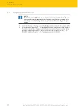
The following figure shows the detection range of the read/write head. The optimum detection
range for the specific application can be set via IO-Link by defining an RSSI value for the specific
application.
4
3
2
1
Fig. 9: Detection range of the read/write head
Position
Meaning
1
Optimum detection range (RSSI value within the set limit value)
2
RSSI limit value
3
Limit of the detection range (RSSI value outside the set limit value)
4
Tag outside the detection range
9.1
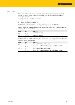
LED indication – TN-Q40…
9.1.1
LED indication – IO-Link mode
LED
Indication
Meaning
Q1/TAG
Off
No tag within the detection range
Yellow
Tag within the optimum detection range
Yellow flashing
(5 Hz)
Tag at the limit of the detection range
Q2/BUSY Yellow flashing
(1 Hz)
Command is executed
ERROR
Red
Error detected
POWER
Green flashing
(1 Hz)
IO-Link mode active


