background image

29

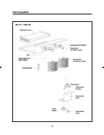
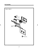
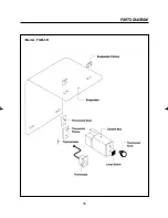
PARTS DIAGRAM

•Model : TGM-5R

Summary of Contents for TGF-13F

Page 1: ...Headquarter 1250 Victoria street CARSON CA 90746 Canada Toll Free 800 627 0032 TEL 562 981 0123 FAX 562 981 0124 www turboairinc com 0210001...

Page 2: ...Commercial Refrigerator Freezer Service Manual Model No TGM 69R TGM 48R TGM 45R TGM 35R TGM 33R TGM 22R TGM 14R TGM 11R TGM 5R TGF 23F TGF 13F TGF 9F...

Page 3: ...Commercial Refrigerator Service Manual Model No TGM 69R TGM 48R TGM 45R TGM 35R TGM 33R TGM 22R TGM 14R TGM 11R TGM 5R...

Page 4: ...26 4 EVAPORATOR PARTS 30 5 LIGHTING PARTS 36 6 SHELF PARTS 40 7 ADVERTISING ADVERTISING FRAME PARTS 41 8 GRILL PARTS 43 7 PARTS LIST 44 8 REPLACEMENT OF MAIN COMPONENTS 51 1 LAMP 51 2 THERMOSTAT AND...

Page 5: ...TGM 69R GLASS DOOR BOTTOM GRILL LEVELING LEG DOOR HANDLE SIGN PANEL LAMP SWITCH EVAPORATOR FAN MOTOR EVAPORATOR FAN BLADE EVAPORATOR COIL KNOB SHELF CONDENSER COIL DRAIN PAN COMPRESSOR EVAPORATOR DRA...

Page 6: ...ELF THERMOSTAT EVAORATOR FAN BLADE TRAY CONDENSER FAN BLADE CONDENSER FAN MOTOR COMPRESSOR EVAPORATOR EVAPORATOR FAN MOTOR CONDENSER FLOURESCENT LAMP Model TGM 48R 35R SIDE SIGN PANEL DOOR DOOR HANDLE...

Page 7: ...FEATURE CHART 4 BOTTOM GRILL LEVELING LEG SHELF SIGN PANEL DOOR GLASS Model TGM 45R 33R SIDE FRONT Model TGM 22R EVAPORATOR COIL DRAIN PAN CONDENSER COIL COMPRESSOR...

Page 8: ...ADE CONDENSER FAN MOTOR DRAIN PAN COMPRESSOR SUCTION PIPE COVER DRAIN HOSE DRAIN ELBOW EVAPORATOR COIL EVAPORATOR FAN BLADE EVAPORATOR FAN MOTOR THERMOSTAT BALLAST SIGN PANEL FLUORES CENT LAMP DOOR HI...

Page 9: ...ENSER COIL CONDENSER FAN MOTOR COMPRESSOR DRAIN PAN EVAPORATOR FAN MOTOR EVAPORATOR COIL BALLAST SIGN PANEL FLUORES CENT LAMP SIDE FLUORESCENT LAMP SIGN PANEL STICKER SHELF LEVELING LEG BOTTOM GRILL M...

Page 10: ...N COMPRESSOR EVAPORATOR COIL EVAPORATOR FAN BLADE EVAPORAOR FAN MOTOR CONDENSER FAN BLADE CONDENSER FAN MOTOR SIDE EVAPORATOR SHELF DRAIN PAN THERMOSTAT CONTROL BOX GASKET DOOR LAMP SWITCH FLUORE SCEN...

Page 11: ...8 Model TGM 5R FEATURE CHART DOOR HANDLE CONDENSER LEVELING LEG SIDE...

Page 12: ...DENSING MOTOR THERMOSTAT CO MP S C LAMP SWITCH LAMP SWITCH POWER BK BK BK WH WH WH WH WH WH BL BL RD RD BK BK BK BK BK BK GY GY WH WH WH WH E RD RD BL BL WH WH WH WH YW YW YW YW YW YW YW YW BALLAST F...

Page 13: ...10 WIRING DIAGRAM Model TGM 35R Model TGM 45R 3 4...

Page 14: ...11 WIRING DIAGRAM Model TGM 33R F L Lamp 17W 3 4 F L Lamp 17W Model TGM 22R...

Page 15: ...DIAGRAM Model TGM 14R BK BK BK BK WH WH GY OL M 2 1 A 3 3 4 F M1 F M2 WH BALLAST 13W THERMOSTAT FL 13W WH BL BL WH WH WH WH WH GN POWER PLUG COMPRESSOR P RELAY S V R C BK BR PK G S Model TGM 11R Mode...

Page 16: ...13 3 REFRIGERANT CYCLE DIAGRAM All the models choose R 134a as a refrigerant R 134a is CFC Free...

Page 17: ...EL PART NAME PART NO MAKER OVERLOAD PART NO MAKER TGM69R 820ARR2B19 TECUMSEH 8300MRAK30 TECUMSEH TGM48R TGM45R 82498 1 TECUMSEH 8300MRAM53 TECUMSEH TGM35R TGM33R 820RR12E72 TECUMSEH 8300MRTM75 TECUMSE...

Page 18: ...Pole Zytel SUNGSHIN Induction 6 TGM35R IS 3220DWSF 3963220501 2P 18W Shaded Pole Zytel SUNGSHIN Induction 3 TGM33R IS 3225DWSL 1 3963329510 2P 18W Shaded Pole Zytel SUNGSHIN Induction 6 TGM22R IS 321...

Page 19: ...AMP MODEL PART NAME PART NO QTY WATT LENGTH DESCRIPTION BULB MAKER TGM69R F32T8 TL850 30200D2800 4 32W 48 TL80 5000K T8 TGM48R F32T8 TL850 30200D2800 2 32W 48 TL80 5000K T8 TGM45R F32T8 TL850 30200D28...

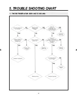
Page 20: ...17 5 TROUBLE SHOOTING CHART 1 THE REFRIGERATOR DOES NOT COOLING...

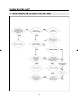
Page 21: ...18 TROUBLE SHOOTING CHART 2 THE REFRIGERATOR DOES NOT COOLING WELL...

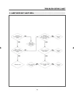
Page 22: ...19 TROUBLE SHOOTING CHART 3 LAMP DOES NOT LIGHT WELL...

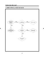
Page 23: ...20 TROUBLE SHOOTING CHART 4 WHEN THERE IS A EXCESSIVE NOISE...

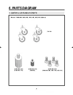
Page 24: ...21 6 PARTS DIAGRAM 1 CASTOR or LEVELING LEG PARTS Model TGM 69R 48R 45R 35R 33R 22R 14R Option LEVELING LEG TGM 14R 11R LEVELING LEG TGM 5R LEVELING LEG TGM 69R 48R 45R 35R 22R 33R Castors...

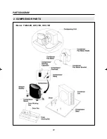
Page 25: ...22 PARTS DIAGRAM 2 COMPRESSOR PARTS Model TGM 69R 48R 45R 35R 33R...

Page 26: ...23 PARTS DIAGRAM Model TGM 22R...

Page 27: ...24 PARTS DIAGRAM Model TGM 14R 11R...

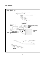
Page 28: ...25 PARTS DIAGRAM Model TGM 5R...

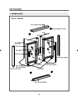
Page 29: ...r Cushion Door Channel Left Door Assembly L Door Assembly M Door Handle Door Glass Door Frame Roller Weight Rope Door Gasket Door M Door Channel Right Door Assembly R Door Roller Door Roller Door Chan...

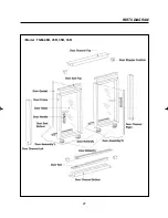
Page 30: ...27 PARTS DIAGRAM Model TGM 48R 45R 35R 33R...

Page 31: ...28 PARTS DIAGRAM Model TGM 22R 14R 11R...

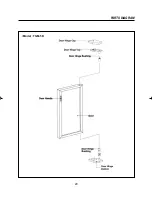
Page 32: ...29 PARTS DIAGRAM Model TGM 5R...

Page 33: ...30 PARTS DIAGRAM 4 EVAPORATOR PARTS Model TGM 48R 35R...

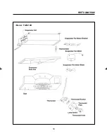
Page 34: ...31 PARTS DIAGRAM Model TGM 69R 45R 33R...

Page 35: ...32 PARTS DIAGRAM Model TGM 22R...

Page 36: ...33 PARTS DIAGRAM Model TGM 14R...

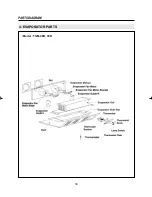
Page 37: ...34 PARTS DIAGRAM Thermostat Thermostat Bracket Thermostat Knob Evaporator Fan Blade Thermometer Evaporator Fan Motor Model TGM 11R...

Page 38: ...35 PARTS DIAGRAM Model TGM 5R...

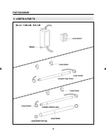
Page 39: ...36 PARTS DIAGRAM 5 LIGHTING PARTS Model TGM 48R 35R 22R...

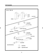
Page 40: ...37 PARTS DIAGRAM Lamp Switch Ballast Lamp for Sign Panel Lamp for Cabinet Liner Lampshield End Cap Lampshield Lamp Socket Lamp Socket Model TGM 69R 45R 33R...

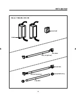
Page 41: ...38 PARTS DIAGRAM Model TGM 14R...

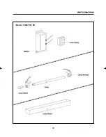
Page 42: ...39 PARTS DIAGRAM Model TGM 11R 5R...

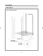
Page 43: ...40 PARTS DIAGRAM 6 SHELF PARTS Model TGM 69R 48R 35R...

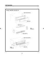
Page 44: ...41 PARTS DIAGRAM 7 ADVERTISING ADVERTISING FRAME PARTS Model TGM 69R 48R 35R...

Page 45: ...42 PARTS DIAGRAM Model TGM 45R 33R 22R 14R...

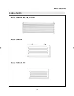
Page 46: ...43 PARTS DIAGRAM 8 GRILL PARTS Model TGM 69R 48R 45R 35R 33R Model TGM 22R Model TGM 14R 11R...

Page 47: ...00 4TM 783SHB TEXAS INS Compressor Overload 3817906500 4TM 293THB TEXAS INS Compressor Running Capactor 400EL15130 230V 10uF Compressor Running Capactor 401RD35050 220V 100uF Condenser 30200K3001 Refe...

Page 48: ...lide Left Door Assembly R 30200J2400 Glass Slide Right Door Assembly R 30217A0311 Glass Slide Right Door Assembly R 30200J2900 Glass Slide Right Door Assembly L 30217A0301 Glass Slide Left Door Assemb...

Page 49: ...pring 30251H0101 Torsion Style Door Hinge Spring 30251G0100 Torsion Style Door Hinge Spring 30252H1100 StainlessT1 5 Bottom Door Channel Top 30287D0103 PVC H Top Door Channel Top 30287J1100 PVC H Top...

Page 50: ...or Stopper Cushion 30252K0200 Rubber Blocks Door Stopper Cushion 30252A0200 Rubber Blocks Evaportaors Control Box 30205A9000 HIPS Evaporator Drain Pan 30211A0101 HIPS Evaporator Drain Pan 30211F0101 H...

Page 51: ...001 PFN 110U 02D GNF 110U 02D Thermostat Bracket 30220A1410 SPG Refer Parts Diagram Thermostat Bracket 30206F1000 SPG Refer Parts Diagram Thermostat Bracket 30220J1000 SPG Refer Parts Diagram Thermost...

Page 52: ...p Shield 30214A0010 ACRYL Lamp Holder 3183005000 SK 5OD28 Lamp Shield 3021101101 PC t0 5 Lamp Shield 30211H0000 PC t0 5 Lamp Shield 30211F0000 PC t0 5 Light Starter 30236A0700 FS 2 Lamp Switch 30281A0...

Page 53: ...T B 30222A0800 PVC H Sign Frame End 30222A0900 PVC H Sign Frame T B 30222H0310 PVC H Sign Frame T B 30222F1902 PVC H Sign Frame End 30222F2103 ABS Dark Gray Sign Frame End L 30222J0100 PVC H Sign Fram...

Page 54: ...T OF MAIN COMPONENTS 1 LAMP FOR ADVERTISING PANEL TGM 69R 48R 45R 35R 33R 1 Separate the Sign Frame End 2 Separate the Sign Panel 3 Separate the Lamp Socket 4 Separate the Lamp out of the Lamp Holder...

Page 55: ...52 5 Take out the Clamp securing wires 6 Separate the Ballast Connectors 7 Unscrew two screws securing the Ballast and replace it REPLACEMENT OF MAIN COMPONENTS...

Page 56: ...53 REPLACEMENT OF MAIN COMPONENTS 1 LAMP FOR CABINET LINER TGM 69R 48R 45R 35R 33R 1 Take out the Doors and separate the Lamp from the Lamp Holder 2 Separate the Lamp Socket...

Page 57: ...54 3 Separate the Lamp Shield End Cap 4 Replace the Lamp REPLACEMENT OF MAIN COMPONENTS...

Page 58: ...PLACEMENT OF MAIN COMPONENTS 1 LAMP TGM 22R 14R 1 Unscrew four screws securing the Sign Frame End and separate the Sign Frame End 2 Separate the Sign Panel 3 Separate the Lamp Sockets and replace the...

Page 59: ...nector of the ballast 5 Unscrew two screws securing the Ballast 6 Separate the Lamp Sockets to replace the Lamp for Cabinet Liner 7 Separate the Lamp Shield End Cap and replace the Lamp REPLACEMENT OF...

Page 60: ...57 REPLACEMENT OF MAIN COMPONENTS 1 LAMP TGM 11R 5R 1 Unscrew two screws securing the Lamp Shield 2 Deassemble the Lamp Shield 3 Separate the Lamp out of the Lamp Holder and replace it...

Page 61: ...35R 33R 1 Unscrew four screws securing the Thermostat control plate 2 Pull out the Thermostat control plate 3 Separate the Receptacles out of the Thermostat and Lamp Switch 4 Separate the Tube of The...

Page 62: ...NTS 5 Separate the Thermostat Knob out of the Thermostat 6 Unscrew two screws securing the Thermostat 7 Separate the Thermostat out of the Thermostat plate 8 Unscrew two screws securing the Thermostat...

Page 63: ...OF MAIN COMPONENTS 2 THERMOSTAT CONTROL AND LIGHT SWITCH TGM 14R 1 Unscrew two screws securing the Thermostat Plate 2 Pull out the Thermostat Plate 3 Separate the Receptacles out of the Thermostat an...

Page 64: ...CEMENT OF MAIN COMPONENTS 4 Separate the Tube of Thermostat from the Evaporator 5 Separate the Thermostat out of the Thermostat Plate 6 Unscrew two screws securing the Thermostat out of the Thermostat...

Page 65: ...ONTROL AND LIGHT SWITCH TGM 11R 1 Unscrew six screws securing the Duct 2 Unscrew four screws securing the Thermostat Plate 3 Separate the Receptacles out of the Thermostat and Lamp Switch REPLACEMENT...

Page 66: ...63 REPLACEMENT OF MAIN COMPONENTS 4 Separate the Tube of Thermostat from the Evaporator Coil 5 Pull out the Thermostat plate 6 Separate the Thermostat out of the Thermostat plate...

Page 67: ...CONTROL AND LIGHT SWITCH TGM 5R 1 Unscrew two screws securing the Control Box 2 Separate the Connectors 3 Unscrew two screws securing the Tube of Thermostat out of the Thermostat Fixture REPLACEMENT O...

Page 68: ...NENTS 3 EVAPORATOR FAN MOTOR BLADE TGM 69R 48R 45R 35R 33R 1 Unscrew four screws securing the Thermostat Plate 2 Unscrew eight screws securing the Duct 3 Separate the Duct 4 Unscrew four screws securi...

Page 69: ...ONENTS 5 Separate the Evaporator Drain Pan 6 Unscrew four screws securing the Evaporator Guide L R and separate them 7 Separate the Vinyl Cover securing the Evaporator Fan Motor 8 Separate the Connect...

Page 70: ...9 Pull out of the Evaporator Fan Motor Harness 10 Unscrew two screws securing the Evaporator Fan Motor Bracket 11 Separate the Evaporator Fan Motor Bracket 12 Unscrew four screws securing the Evapora...

Page 71: ...E TGM 22R 1 Unscrew the screw securing the Evaporator Fan Motor Guard 2 Separate the Evaporator Fan Motor Cover 3 Replace the Evaporator Fan Motor 4 Unscrew four screws securing the Thermostat Plate R...

Page 72: ...69 REPLACEMENT OF MAIN COMPONENTS 5 Separate the Thermostat Plate Pull out the tube of Thermostat out of the Evaporator Coil 6 Unscrew four screws securing the Duct 7 Separate the Duct...

Page 73: ...Separate the Duct Caution Pulling the Duct to the front can cause the Fan Blade to be bent REPLACEMENT OF MAIN COMPONENTS 3 Unscrew four securing the Evaporator Fan Motor Bracket 4 Separate the Connec...

Page 74: ...OF MAIN COMPONENTS 5 Unscrew two screws securing the Evaporator in case of replacing it 6 Separate Suction Pipe Cover on the Rear Cabinet 7 Separate the Sealing Tube 8 Replace the Suction Pipe with w...

Page 75: ...Evaporator Coil Caution Pulling the Evaporator can cause the Cabinet Liner to be scratched 10 Separate the Evaporator Coil out of the Evaporator Drain Pan and repair the Evaporator Coil REPLACEMENT O...

Page 76: ...3 EVAPORATOR FAN MOTOR BLADE TGM 11R 1 Unscrew the screws securing the Duct 2 Unscrew the screws securing the Thermostat Plate 3 Separate the harness out of the Thermostat and Lamp Switch 4 Separate...

Page 77: ...3R 1 Unscrew four screws securing the Bottom Grill 2 Separate the Compressor Harness out of the Switch Box 3 Unscrew four screws securing the Compressor Base 4 Pull the Compressor Base and separate th...

Page 78: ...ENSER FAN MOTOR BLADE TGM 22R 1 Unscrew four screws securing the Bottom Grill 2 Separate the Connector out of the Switch Box 3 Unscrew four screws securing the Compressor Base 4 Pull the Compressor Ba...

Page 79: ...CONDENSER FAN MOTOR BLADE TGM 14R 11R 1 Unscrew four screws securing the Bottom Grill 2 Separate the Connector out of the Switch Box 3 Unscrew four screws securing the Condenser Fan Motor Bracket 4 Pu...

Page 80: ...77 REPLACEMENT OF MAIN COMPONENTS 5 Separate the Fan Motor Bracket 6 Separate the nut and replace the Fan Blade...

Page 81: ...78 REPLACEMENT OF MAIN COMPONENTS 5 DOOR TGM 22R 14R 1 Separate the Sign Frame End and Sign Panel 2 Separate the Door Hinge Top and Door...

Page 82: ...Commercial Freezer Service Manual Model No TGF 23F TGF 13F TGF 9F...

Page 83: ...Y POWER SWITCH LAMP SWITCH FRONT EVAPORATOR FAN MOTOR BLADE EVAPORATOR FAN MOTOR EVAPORATOR COIL BACK GUARD AIR BAFFLE BACK CASTER COMPRESSOR CONDENSER FAN MOTOR CONDENSER COIL CASTER WITH BRAKE BOTTO...

Page 84: ...9F 2DOOR TGF 13F LAMP SWITCH DECORATION COVER R FRONT GLASS DECORATION COVER L FRONT LAMP HOLDER BALLAST INSULATOR TOP LAMP SOCKET LAMP LAMP SWITCH LINER COVER LINER COVER HEATER EVAPORATOR URT FOAM A...

Page 85: ...83 FEATURE CHART COMPRESSOR DRYER POWER CORD CONDENSER COIL COMPRESSOR COMPRESSOR RELAY ASSEMBLY CONDENSER FAN MOTOR REAR GRILL BACK Model TGF 13F 9F...

Page 86: ...A 13 DOOR FRAME FIXTURE B 14 DOOR FRAME FIXTURE D 15 LAMP MOUNTING BASE 16 DOOR SIGN PANEL 17 LAMP SOCKET WITH SPRING 18 LAMP SOCKET WITHOUT SPRING 19 LAMP SOCKET BRACKET 20 LAMP SHIELD FIXTURE 21 LA...

Page 87: ...TGF 23F Evaporator Fan TGF 23F Lamp Fan Motor Connectors Evaporator Fan Motor Blade Evaporator Thermal Evaporator Coil Defrost Heater F Sensor Heater Connectors Sensor Connectors Evaporator Fan Motor...

Page 88: ...86 3 WIRING DIAGRAM Model TGF 23F Model TGF 13F...

Page 89: ...87 WIRING DIAGRAM Model TGF 9F...

Page 90: ...CE Comp Assembly TGF 9F PTC 068 3017906900 4TM 783SHB 3817910600 DAEWOO TEXAS INSTRUNENT 3 COMPRESSOR CAPACITOR MODEL STARTING PART No RUNNING PART No MAKER Note TGF 23F 160V 315 F 400V 30 F TECUMSEH...

Page 91: ...25W 0 3A Rapid 9 FLUORESCENT LAMP MODEL PART NAME PART No NUMBER WATT LENGTH DESCRIPTION BULB MAKER TGF 23F F17T8 TL950 30236H0500 1 17W 12 TL950 5000K T8 PHILIPSorGE F48T12 CW VHO 30236R1000 1 110W 4...

Page 92: ...t during defrost mode InsideTemperature can be set by the user Not controllable during Turbo Freeze mode The default temperature setting is 7 F By pushing up down button you can set the inside tempera...

Page 93: ...up down button 3 88 LED will indicate real inside temperature after your setting 4 Buzzer rings 1 time whenever each button is pressed 5 Compressor automatically turns on and off by F sensor Except e...

Page 94: ...g of when unit was plugged in 1 Defrost step Pre cool Heater Pause Fan Delay Comp on off off on F fan motor on off off off C fan motor on off off on Heater off on off off Max time 30 min 40 min 3 min...

Page 95: ...he same as that of the defrost mode 1 Compressor will not start for 3 minutes after compressor is off even though the F sensor is at on point 1 Compressor will not strat for 3 minutes after power fail...

Page 96: ...ted If F sensor temp is higher than 28 4 F then heater goes off Heater turns on for 20 minutes if F sensor is in error mode too C1 Cycle Comp When the temperature of the Normal operation Malfunction D...

Page 97: ...050 220V 100uF 1 Compressor Capacitor Fixture 3022006000 SPG 1 Condenser Condenser Coil 30200R0200 TGF 23F 1 Condenser Coil 30200N5300 Refer Parts Diagram 1 Condenser Coil 30200N5201 Refer Parts Diagr...

Page 98: ...URT Foam Assembly 4034L05103 TGF 9F 1 Evaporator Top 3020000702 ROLL BOND AL 1 Evaporator Top 3020000305 ROLL BOND AL 1 Insulation Cover 30214N0800 PVC H 1 Insulation Cover 30214N0700 PVC H 1 Insulati...

Page 99: ...6A 1 1 Lamp Socket 30279N0100 Including Harnes 1 Lamp Socket 3027900113 Including Harnes 1 Decoration Cover Left 30214N0100 ABS Plastic Gray 1 1 Decoration Cover Right 30214N0200 ABS Plasric Gray 1 1...

Page 100: ...TP 1 Shelf Shelf Standard 30220L1001 SUS304 2B 4 Shelf 30278R0100 Wire White 4 Shelf Clip 30220L0900 PA 6 16 Back Guard Air Baffle Back 30250R0200 Wire White 2 Thermostat Themperture Control 30283N01...

Page 101: ...NT OF MAIN COMPONENTS 99 7 1 BOTTOM GRILLE PARTS MAIN PCB TRANSFORMER POWER RELAY DISPLAY P C B LAMP SWITCH POWER SWITCH A Remove Bottop Grille by unscrewing the four screws B Remove the Bracket of Di...

Page 102: ...100 REPLACEMENT OF MAIN COMPONENTS C Disconnect Connectors and receptacles Replace the Power Switch Lamp Switch or Display P C B D Remove the electrical box Switch Box cover...

Page 103: ...101 REPLACEMENT OF MAIN COMPONENTS E Remove the Fixture F Replace the Ballast for inner Cabinet Lamp 110W 1 Pull out the Ballast Base 2 Replace the Ballast...

Page 104: ...102 REPLACEMENT OF MAIN COMPONENTS G Replace the Main P C B Transformer and Power Relay 1 Pull out the Base 2 Replace the parts...

Page 105: ...7 2 REPLACING DOOR A Disassemble bottom grille as described section 7 1 A B C D B Disconnect the door heater wire and lamp wire C Remove the Sign Frame Left Right by unscrewing the four screwes of ea...

Page 106: ...104 REPLACEMENT OF MAIN COMPONENTS D Pull out sign panel to the Right Side F Remove the sign panel frame Bottom Replace the Ballast Sign Panel...

Page 107: ...105 REPLACEMENT OF MAIN COMPONENTS E Remove the harness of door switch Replace door Switch G Remove the door hinge top H Lift the door and pull out the door wires...

Page 108: ...VISION CREATIVE INC...

Reviews: