3
ASSEMBLY
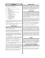
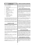
Ensure all parts are present (fig. 1):
A
Meter
B
Safety tether key with cord (+ 1 spare key)
C
Power cord
D
Left handlebar
E
Handlebar bracket cover
F
Right handlebar with attached meter base
G
Main frame
Assembly kit including
H
2 x M8 x 80 mm allen screws
I
2 x flat washers
J
1 x white decorative cap
K
2 x plastic cable holders
6 mm allen wrench
10/11 open-end wrench
T-Lube bottle
I
f necessary, contact the dealer and give the model, serial
number and spare part number from the spare part list at the
back of the manual.
Left, right, front and back are as seen from the exercising
position. Assemble the treadmill as follows:
HANDLEBARS
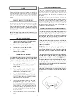
NOTE! Do not tighten any fixing screws before both handle-
bars are completely assembled.
Remove and dispose the silicate bag from the bottom of the
right handlebar. The purpose of this bag is simply to absorb
dampness during transportation and storage.
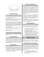
Install the right handlebar in place at the front right corner of
the treadmill and secure it using the allen screw and washer.
Press the white decorative cap onto the lower end of the
right handlebar (fig. 2).
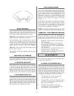
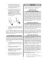
Attach the left handlebar to the running deck side rail using
an allen screw and a washer. If necessary, lean the treadmill
on one side with help of another person (fig. 3).
NOTE! Make sure that the cable operating the lift spring is
not pinched or forced to make any tight curves.
Attach the handlebar bracket cover by snapping it into place
over the lower end of the left handlebar.
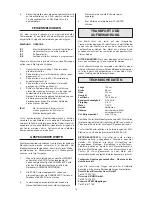
Push the left handlebar inside the plastic meter base
attached to the right handlebar. When the top of the left
handlebar is touching the top of the right handlebar, tighten
the screws in the bottom of the meter base, while ensuring
the handlebars are held securely together (fig. 4).
NOTE! Be careful not to pinch or otherwise damage the flat
ribbon cable that runs inside the right handlebar.
METER CABLE
Plug the lower end of the flat ribbon cable coming out from
the right sidecover into the upper end coming out of the right
handlebar. Thread the connected cable inside the hole in the
sidecover and push the cover plug on the through hole so
that the cable will not be damaged (fig. 5).
LIFT CABLE
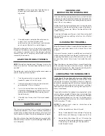
Lift and tilt the treadmill on its right side. Route the lift cable
as shown in the figure 6. Attach the wire coming out of the
end of the lift cable in its place through the pivot bracket (fig.
7). Adjust wire length by turning the adjuster screw on the
cable to the very end. Make sure that the end of the cable is
inside the adjuster totally.
Press the wire end in its place in the notch of the black
alligator clip. The alligator clip adjusts the gas spring. If
necessary, press the jaws of the clip together to get the wire
end in its place. Secure the adjustment of the lift cable by
tightening the locking nut with an open-end wrench.
Attach the plastic cable holders below the left side rail and
press the lift cable to the holders (see arrow in fig. 6).
Lift the treadmill back into the upright position.
Check the functioning of the lift mechanism as follows:
Stand on the rear end of the treadmill. Move the elevation
control lever located on the left handlebar forward. The back
of the treadmill will gradually go down increasing the
elevation. To decrease the elevation move to the front of the
treadmill. Move the elevation control lever and the rear half
of the treadmill will begin to rise decreasing the elevation.
If the elevation mechanism does not function as described
above, tilt the treadmill on its right side again. Loosen the
locking nut of the of the lift cable and adjust the cable tension
with the adjuster screw until the lift mechanism functions
properly. Secure the adjustment by tigthening the locking
nut.
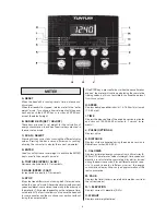
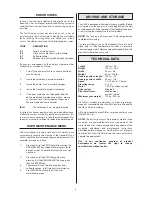
METER
Plug in the pulse cable and flat ribbon cable connectors on
the back side of the display. Tuck the cables inside the meter
base and carefully slide the meter onto the base (fig. 8).
NOTE! Be careful not to pinch or otherwise damage the
cables. Remove the protecting film from the display.
PLUGGING IN THE TREADMILL
Plug the socket end of the power cord into the treadmill at
the lower right front corner.
Before connecting the device to a power source make sure
that the voltage is correct from the type plate (230 V).
Summary of Contents for J 440
Page 58: ...58...

