

Page 4 of 8
GENERAL INFORMATION
COMPONENTS
Linear unidirectional feeders are used to transfer the parts delivered by a feeding unit to a pick-up area, through a channel fixed
to the upper tray.
This type of vibrator is also useful to have a number of oriented parts
“
in store
”
along the channel.
The parts flowing to the orienting device can be interrupted by a sensor system whenever the channel gets full, and restarted as
soon as some of the parts have been used.
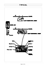
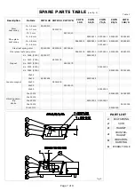
Linear unidirectional feeders consist of three elements :
- A vibrating base equipped with one magnet.
- A conveyor channel.
- A control box, for feed control.
LINEAR UNIDIRECTIONAL FEEDERS
OPERATING PRINCIPLE
When electrical current flows through an electromagnet, integral with a mass, the leaf springs that connect the vibrating base to
the channel bend. This reaction of the leaf springs generates a motion that ultimately causes forward movement of the material
along the channel.
Before using the vibrator, read through this booklet carefully. This guide contains safety instructions for set-up, operation and
maintenance. All operations must be carried out in such a way as not to damage the components.
HANDLING AND TRANSPORTATION
The product is shipped in a wood box, fixed by means of small beams.
In order to protect the operators involved in handling operations, the vibrators whose weight does not exceed 15 Kg must be
taken out the package using eye-bolt G (see fig. 2), mounted on the vibrators themselves.
SET-UP
Before installing the vibrator, make sure that set-up area is suitable for the overall dimensions, weight and working conditions of
the system.
The support must be rigid and well fastened.
If a support with unsuitable dimensions is used, it will start vibrating, causing incorrect operation of the system.
For fastening, use the threaded holes provided in the vibration-damping feet and / or bases according to the type of vibrations.
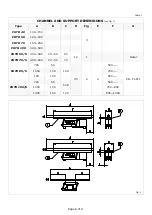
Please refer to Table 4, which specifies the dimensions of the holes to be drilled in the supports.
START-UP
Store this booklet in a safe place for future reference.
The linear vibrator must be equipped with a control box, with power and frequency suited to the vibrator it has to control.
If possible, the control box should be installed in an airy room, since in these conditions the components last longer.
When the vibrator and its control box have been installed correctly and all checks have been completed, the unit will be ready to
start.
Before connecting the unit to the power mains, carry out the following checks:
- Mains voltage - it must be the same as the value written on the unit tag.
- Mains frequency - it must be the same as the value written on the unit tag.
- Power supply cable - its size must be suitable for the power input required by the unit.
- Ground connections as appropriate.
- Positioning with respect to a round automatic distributor or other units - the various channels must be laid out so as not to
touch or clash against one another, to avoid damage or malfunctioning.
Important
: Set-up and start-up operations must be carried out by qualified personnel, who should read and understand the in-
structions reproduced in this booklet.
MOUNTING AND DISMOUNTING THE CHANNEL
Important
: Before carrying out any operation, turn the power supply off.
When installing the unit, or during operation and maintenance, it may be necessary to dismount the channel from the vibrating
base to remove it. To dismount it, proceed as follow :
DISMOUNTING:
For type CHTR 40-50-70-85/S-100/S, loosen the channel fastening screws and remove the channel from its support.
For type CHTR 50/S and CHTR 75/S, simply loosen the channel fastening jaws to remove the channel.
MOUNTING:
Repeat the above procedure in reverse order, and be careful to re-position the channel in the original location.
Summary of Contents for CHTR 40
Page 3: ...Page 3 of 8 TYPICAL...