

7
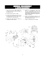
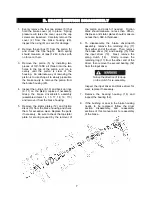
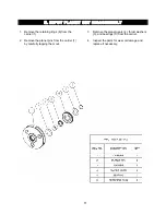
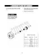
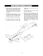
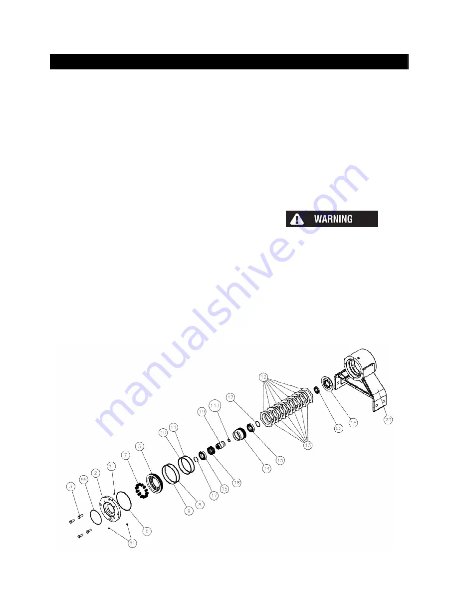
B. BRAKE SECTION DISASSEMBLY
1. Evenly remove the four cap screws (3) that
hold the brake cover (2) in place. Spring
pressure will raise the cover up as the cap
screws are loosened. Carefully remove the
cover (2) from the brake housing (20).
Inspect the o-ring (6) on cover for damage.
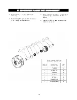
2. Remove the springs (7) from the piston (5)
and check the free height. Each spring
should measure at least 1.240 inches with
no force on them.
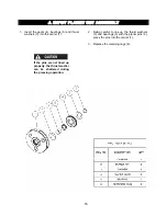
3. Remove the piston (5) by installing two
pieces of 3/8”-16NC all thread into the two
holes in the top of the piston and run in
evenly until the piston is clear of the
housing. An alternate way of removing the
piston is to use shop air to slowly pressurize
the brake cavity to remove the piston from
the brake housing (20).
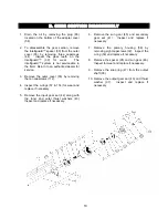
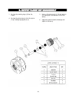
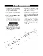
4. Inspect the o-rings (8, 10) and back up rings
(9, 11) on the piston, replace if necessary.
Grasp the brake driver/clutch assembly
(assembled items 14, 15, 17, 18, 19, 113)
and remove it from the brake housing.
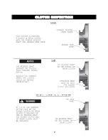
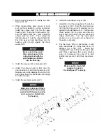
5. Remove the stator plates (12) and friction
discs (13) from the brake housing and check
them for excessive wear. Replace the parts
if necessary. Be sure to check the top stator
plate for scoring caused by the removal of
the piston and polish if needed. Friction
discs should measure no less than .055-in.
thickness and stator plates should measure
no less than .068-in thickness.
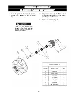
6. To disassemble the brake driver/clutch
assembly, remove the retaining ring (17)
from either end of the driver. Then, remove
the brake driver (14) and bearing (15) from
the input driver (19). Next, remove the
sprag clutch (18). Finally, remove the
retaining ring (17) from the other end of the
driver, then remove the second bearing (52)
from the input driver.
Notice the direction of lock-up
on the clutch for re-assembly.
Inspect the input driver and brake driver for
wear, replace if necessary.
7. Remove the bearing housing (16) and
inspect the bearing (52).
8. If the bushing or seal in the brake housing
needs to be replaced, follow the drum
section disassembly and reassembly
sections of this manual prior to reassembly
of the brake..
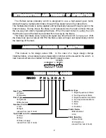
Summary of Contents for Rufnek Intelliguard 80
Page 9: ...9 CLUTCH INSPECTION ...
Page 26: ...26 VISCOSITY CHART ...


