10
H. BRAKE SECTION
ASSEMBLY
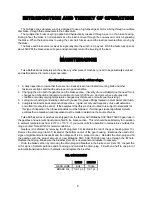
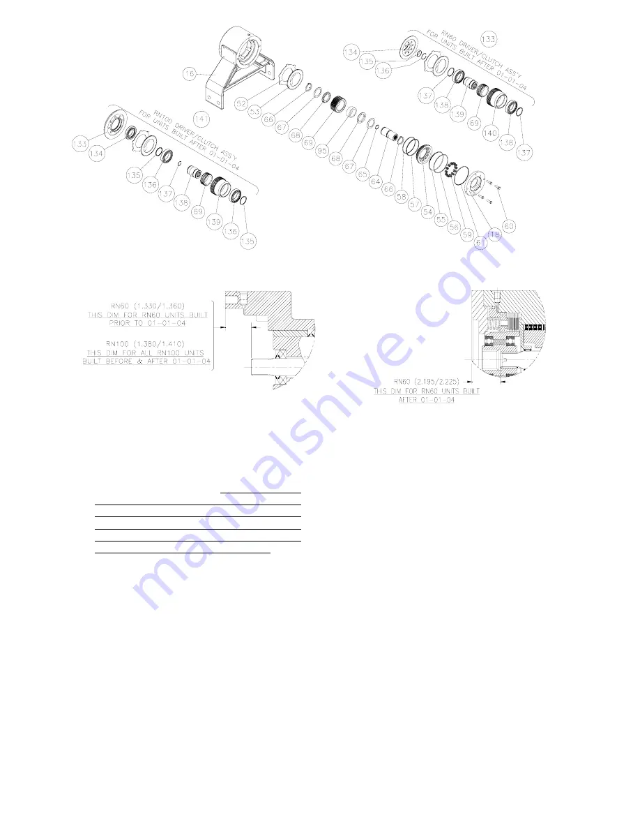
1. Measure the distance as shown above. If
needed add shims part number 33324 and
994188 inside input driver (64) to achieve
above noted dimension.
(Note: For RN60
units built after 01-01-04 measuring and
shimming is done after installing the cover (18)
as shown above. Refer to Field Service
Literature (FSL-0017) for RN45-130 product
enhancements to the driver/clutch ass’y
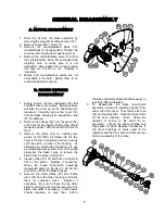
2. Re-assemble the driver/clutch assembly
making sure the clutch is installed properly
and checking to make sure the cam clutch is
free turning in the pay in direction. Install the
driver/clutch assembly onto input shaft (21A).
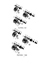
3. Install the stator plates (52) and friction discs
(53) starting with a stator plate and alternating
between friction discs and stator plates until
eight stator plates and seven friction discs are
used. Note: Soak friction discs in hydraulic oil
before installation
4. Coat the piston O.D. with oil or grease and
install the piston into the brake housing by
gently tapping it down until it is seated making
sure not to damage the o-rings or back-up
rings.
5. Install the springs into the spring pockets. If
working in a horizontal position, coat the
6. bottom of each spring with chassis lube to
keep it in position.
7. Coat the o-ring (61) with oil or grease and
install it into the groove on the brake cover
(18).
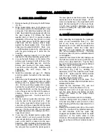
8. Install the cover onto the brake housing using
the capscrews (60). Then draw it down
evenly, alternating between opposite hex
bolts. Make sure that the cover is aligned
properly with the brake housing to orient the
motor as it should be.
9. Check the brake release with a portable
hydraulic pump. Full release should be
obtained at 340psi, plus or minus 20psi. Also,
check the brake for proper operation by
applying 280psi to the brake port and adapting
a torque wrench to the input shaft. The torque
in the payout should be 95 to 115 ft-lbs.
10. Install the motor (63) and secure with the four
capscrews (30). Tighten the capscrews to the
proper torque.
Note:
Make sure you install
the motor with the belly of it down and the
case drain port up.
Install the counterbalance
block. Hook up the brake line to the top of the
brake housing (16). Fill the brake and
gearbox with the proper oil.


