A S S E M B L Y I N S T R U C T I O N S
Leg Press Station Rev0
A m e r i c a ’ s P r e m i e r E x e r c i s e E q u i p m e n t
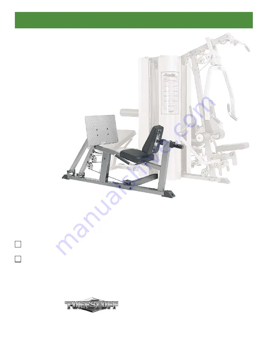
Apollo Modular Gym System
Leg Press Station
Standard
Deluxe
Revision Date 08-23-05
Page 1: ...S E M B L Y I N S T R U C T I O N S Leg Press Station Rev0 A m e r i c a s P r e m i e r E x e r c i s e E q u i p m e n t Apollo Modular Gym System Leg Press Station Standard Deluxe Revision Date 08 23 05 ...
Page 2: ...eatly organize and identify all parts according to the Exploded View Diagram on Fold out Pg 7 and the Parts List on Pg 8 Tool Requirements 1 One 9 16 combination wrench 2 One ratchet 3 One 9 16 socket 4 One rubber mallet 5 Multi purpose grease 6 Measuring tape 7 Utility knife Introduction Specifications 1 Maximum Wt Capacity 200 Lbs 2 Total Machine Weight 150 Lbs Hardware Measurement Diagram Note ...
Page 3: ...Hex Head Cap Screw 3 8 16 X 2 3 4 104 two Flat Washers SAE 3 8 94 and one Nylon Insert Jam Lock Nut 3 8 16 123 Next attach two Pulleys 4 1 2 Rd 78 Labeled D2 D4 to the Ful crum with Brackets 52 using two Hex Head Cap Screws 3 8 16 X 1 3 4 101 four Flat Washers SAE 3 8 94 and two Nylon Insert Jam Lock Nuts 3 8 16 123 52 47 D4 D2 D3 D1 FIG 6 Locate one of the Adjustable Pulley Brackets 45 and at tac...
Page 4: ... and thread it to the bolt of the Leg Press Cable 55 55 90 176 56 FIG 9 Next attach the Swivel Cable End 56 to the Fulcrum with Brackets 52 using one Hex Head Cap Screw 3 8 16 X 1 3 4 101 two Flat Washers SAE 3 8 94 one Nylon Insert Jam Lock Nut 3 8 16 123 52 56 55 FIG 10 Route the Leg Press Cable 55 around the Pulley 4 1 2 Rd 78 Labeled D1 Next route under then up the Pulley 4 1 2 Rd 78 Labeled D...
Page 5: ...ing Diagram on fold out page 6 for further detailed illustration of the Leg Press Cable 55 routing 1 46 55 D6 D5 FIG 14 Attach the Right Handle 31 and the Left Handle 32 to the Leg Press Main Frame 47 in the position as shown above using two Hex Head Cap Screws 3 8 16 X 3 1 4 105 four Flat Washers SAE 3 8 94 and two Nylon Insert Lock Nuts 3 8 16 125 31 32 47 FIG 13 Continue to route up and over th...
Page 6: ...ch the Adjustable Back Pad Tube 49 to the Back Pad 54 using two Hex Head Cap Screws 3 8 16 X 1 1 4 99 and two Flat Washers SAE 3 8 94 140 49 54 FIG 17 Insert the assembled Adjustable Back Pad Tube 49 to the Leg Press Main Frame 47 54 47 179 49 FIG 18 Caution It is strongly recommended to use another person in assisting with this assembly Attach the Foot Plate 48 to the Foot Plate Bracket 50 using ...
Page 7: ...1 76 ALUMINUM CAP 1 RD CAP 100 BNH0537 2 144 PLASTIC TUBE GUIDE W LIP TEETH 2 1 4 SQ BNH0059 2 78 ALUMINUM PULLEY 3 8 X 4 1 2 BNH0069 7 153 RUBBER BUMPER 3 8 X 2 1 2 BNH0511 1 80 BEARING 6203 W TWO 1 2 BUSHINGS BNH0835 8 156 RUBBER GRIP 1 ID X 125 X 8 BNH0966 2 82 BRONZE BUSHING 3 8 X 1 2 X 5 16 BNH0737 2 169 SOCKET SET SCREW ALLOY 10 32 X 1 8 BNH0473 4 89 FINISHED HEX NUT B O 1 2 13 BNH0201 2 171...
Page 8: ...y elect at TuffStuff s facility in Pomona California without charge to purchaser for either parts or labor Purchaser is responsible for installation of repaired or replaced parts and all transportation and insurance costs on returned or replaced equipment to and from TuffStuff s facility in Pomona THE FOREGOING SHALL CONSTITUTE THE SOLE REMEDY OF THE PURCHASER AND THE SOLE LIABILITY OF TUFFSTUFF W...