background image

III 

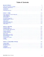
Table of Contents - 

Nitro 275RS

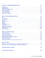
Section 4 - Troubleshooting / Maintenance 

4-1

Tire Safety  . . . . . . . . . . . . . . . . . . . . . . . . . . . . . . . . . . . . . . . . . . . . . . . . . . . . . . . . . . . . . . . . . . . . . . . . . . . . .4-1

Hydraulic Safety   . . . . . . . . . . . . . . . . . . . . . . . . . . . . . . . . . . . . . . . . . . . . . . . . . . . . . . . . . . . . . . . . . . . . . . . .4-1

Fluids & Lubricants  . . . . . . . . . . . . . . . . . . . . . . . . . . . . . . . . . . . . . . . . . . . . . . . . . . . . . . . . . . . . . . . . . . . . . .4-2

Adjusting Apron Chain Tension  . . . . . . . . . . . . . . . . . . . . . . . . . . . . . . . . . . . . . . . . . . . . . . . . . . . . . . . . . . . . .4-2

Every 10 Hours/Daily . . . . . . . . . . . . . . . . . . . . . . . . . . . . . . . . . . . . . . . . . . . . . . . . . . . . . . . . . . . . . . . . . . . . .4-3

Every 10 Hours/Daily . . . . . . . . . . . . . . . . . . . . . . . . . . . . . . . . . . . . . . . . . . . . . . . . . . . . . . . . . . . . . . . . . . . . .4-4

Every 40 hrs / Weekly  . . . . . . . . . . . . . . . . . . . . . . . . . . . . . . . . . . . . . . . . . . . . . . . . . . . . . . . . . . . . . . . . . . . .4-5

Every 400 hrs / Annually  . . . . . . . . . . . . . . . . . . . . . . . . . . . . . . . . . . . . . . . . . . . . . . . . . . . . . . . . . . . . . . . . . .4-5

Section 5 - Parts Breakdowns & Lists 

5-1

Hitch   . . . . . . . . . . . . . . . . . . . . . . . . . . . . . . . . . . . . . . . . . . . . . . . . . . . . . . . . . . . . . . . . . . . . . . . . . . . . . . . . .5-2

Front Shields  . . . . . . . . . . . . . . . . . . . . . . . . . . . . . . . . . . . . . . . . . . . . . . . . . . . . . . . . . . . . . . . . . . . . . . . . . . .5-4

Front Apron Drive   . . . . . . . . . . . . . . . . . . . . . . . . . . . . . . . . . . . . . . . . . . . . . . . . . . . . . . . . . . . . . . . . . . . . . . .5-6

Driveline. . . . . . . . . . . . . . . . . . . . . . . . . . . . . . . . . . . . . . . . . . . . . . . . . . . . . . . . . . . . . . . . . . . . . . . . . . . . . . .5-8

Rear Apron Drive . . . . . . . . . . . . . . . . . . . . . . . . . . . . . . . . . . . . . . . . . . . . . . . . . . . . . . . . . . . . . . . . . . . . . . .5-10

Endgate  . . . . . . . . . . . . . . . . . . . . . . . . . . . . . . . . . . . . . . . . . . . . . . . . . . . . . . . . . . . . . . . . . . . . . . . . . . . . . .5-12

Beaters   . . . . . . . . . . . . . . . . . . . . . . . . . . . . . . . . . . . . . . . . . . . . . . . . . . . . . . . . . . . . . . . . . . . . . . . . . . . . . .5-14

Floor & Side Boards   . . . . . . . . . . . . . . . . . . . . . . . . . . . . . . . . . . . . . . . . . . . . . . . . . . . . . . . . . . . . . . . . . . . .5-16

Single Axle . . . . . . . . . . . . . . . . . . . . . . . . . . . . . . . . . . . . . . . . . . . . . . . . . . . . . . . . . . . . . . . . . . . . . . . . . . . .5-18

Tandem Axle (w/o Scales)  . . . . . . . . . . . . . . . . . . . . . . . . . . . . . . . . . . . . . . . . . . . . . . . . . . . . . . . . . . . . . . . .5-20

Tandem Axle (w/ Scales)  . . . . . . . . . . . . . . . . . . . . . . . . . . . . . . . . . . . . . . . . . . . . . . . . . . . . . . . . . . . . . . . . .5-22

Apron Runners   . . . . . . . . . . . . . . . . . . . . . . . . . . . . . . . . . . . . . . . . . . . . . . . . . . . . . . . . . . . . . . . . . . . . . . . .5-24

Hydraulic Layout  . . . . . . . . . . . . . . . . . . . . . . . . . . . . . . . . . . . . . . . . . . . . . . . . . . . . . . . . . . . . . . . . . . . . . . .5-26

Section 6 - Optional Features 

6-1

Light Kit Assembly  . . . . . . . . . . . . . . . . . . . . . . . . . . . . . . . . . . . . . . . . . . . . . . . . . . . . . . . . . . . . . . . . . . . . . . .6-2

Light Kit Wiring Harness  . . . . . . . . . . . . . . . . . . . . . . . . . . . . . . . . . . . . . . . . . . . . . . . . . . . . . . . . . . . . . . . . . .6-4

Flow Control Hydraulics. . . . . . . . . . . . . . . . . . . . . . . . . . . . . . . . . . . . . . . . . . . . . . . . . . . . . . . . . . . . . . . . . . .6-6

Electric Flow Control Wiring   . . . . . . . . . . . . . . . . . . . . . . . . . . . . . . . . . . . . . . . . . . . . . . . . . . . . . . . . . . . . . . .6-8

N750LC (GT400) / N750LCNT460 Scales   . . . . . . . . . . . . . . . . . . . . . . . . . . . . . . . . . . . . . . . . . . . . . . . . . . .6-10

N750LCNT8000 Scales . . . . . . . . . . . . . . . . . . . . . . . . . . . . . . . . . . . . . . . . . . . . . . . . . . . . . . . . . . . . . . . . . . 6-11

Chain Drive Hydraulics  . . . . . . . . . . . . . . . . . . . . . . . . . . . . . . . . . . . . . . . . . . . . . . . . . . . . . . . . . . . . . . . . . .6-12

Reversing the Apron Chain (with Optional Flow Control)   . . . . . . . . . . . . . . . . . . . . . . . . . . . . . . . . . . . . . . . .6-12

Section 7 - PTOs 

7-1

39850 - PTO. 375,450,525,600,750 (V80-141P028359-028028-CV80-CLS) . . . . . . . . . . . . . . . . . . . . . . . . . .7-2

39852 - PTO. 600, 750 (T60-086P265011-306028-CLS(2500NM) . . . . . . . . . . . . . . . . . . . . . . . . . . . . . . . . . .7-4

Torque Value Chart - Imperial 

VII

Torque Value Chart - Metric 

VIII

Summary of Contents for Nitro 275RS

Page 1: ...40299 Rev 1 1 18 04 2018 Operator s Manual Parts Manual...

Page 2: ...the use or misuse by his employees or others Nitro Apron Chain Warranty Tubeline Manufacturing Ltd offers a limited lifetime non transferable warranty to the original purchaser of a Nitro manure spre...

Page 3: ...ning 1 5 Safety Signs 1 5 How to Install Safety Signs 1 5 Safety Sign Locations 1 6 Safety Decals 1 7 Section 2 Operation 2 1 Preparation Safety 2 1 Hydraulic Requirements 2 1 PTO Horsepower Requireme...

Page 4: ...Side Boards 5 16 Single Axle 5 18 Tandem Axle w o Scales 5 20 Tandem Axle w Scales 5 22 Apron Runners 5 24 Hydraulic Layout 5 26 Section 6 Optional Features 6 1 Light Kit Assembly 6 2 Light Kit Wirin...

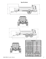
Page 5: ...Nitro 275 Cu ft Struck 220 Heaped Cu ft 290 Inside Width 62 Inside Depth 32 Inside Length 160 Loading Height 69 Overall Length 23 5 Beater Diameter 34 Beater Speed 420 RPM Axle Type Single Tandem Hub...

Page 6: ...ron chain is operated from the tractor cab and controls the speed of materials being fed through the beaters The apron chain and rear lift gate are operated using the tractor s hydraulic power outputs...

Page 7: ...dicates a potentially hazardous situation that may result in injury WARNING Indicates a potentially hazardous situation that could result is serious injury or death DANGER Indicates a hazardous situat...

Page 8: ...place any decals that may be missing or that are not readable Location of the decals is indicated in this manual Do not operate this machine while under the influence of drugs or alcohol Review the sa...

Page 9: ...RY OR DEATH 1 This safety section is intended to point out some of the basic safety situations that can be encountered during the normal operation and maintenance of the Nitro Manure Spreader and to s...

Page 10: ...Keep all shields in place If shield removal becomes necessary for repairs replace the shield prior to use 3 Replace any safety sign or instruction sign that is not readable or missing Location of suc...

Page 11: ...quickly in an emergency 6 Train all new personnel and review instructions frequently with existing workers Be certain only a properly trained and physically able person will use the machinery A perso...

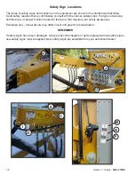
Page 12: ...ous safety signs the types of warning and the area or proper function related to that area that requires your safety awareness Examples only Actual decals may differ in text and graphic representation...

Page 13: ...Item E Part DE42784 See Operators Manual for decal explanation Item D Part DE42782 Reversing apron chain while spreader is fully loaded will cause front apron shaft breakage Item C Part DE42772 Rever...

Page 14: ...1 8 Section 1 Safety Nitro 275RS Safety Decals Item H Part DE39397 Item I Part DE23838 Item G Part DE23836 Item F Part DE23845 Item J Part DECANADA...

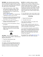
Page 15: ...he Nitro Manure Spreader should always be parked on a level dry area that is free of debris and foreign objects Follow this procedure when attaching 1 Clear the area of bystanders and remove foreign o...

Page 16: ...to avoid damage Before Using 1 Read the Nitro Operator s Manual Do not operate the spreader until the safety precautions in this manual and the decals on the spreader have been read and understood by...

Page 17: ...fore servicing adjusting repairing or unplugging 8 Never use alcohol or drugs which can hinder alertness or coordination while operating this equipment Consult your doctor about operating this machine...

Page 18: ...preader The manure consistency will determine how full your spreader can be loaded Solid manure can usually be loaded level to slightly heaped Wet materials are heavier and may limit loading NOTICE It...

Page 19: ...ure electrical outlets and tools are properly grounded Use adequate light for the job at hand 3 Never attempt to service hydraulic applications while pressurized or with engine running 4 Never work un...

Page 20: ...ure to stop tractor and wait for all moving parts to stop before servicing or unplugging WARNING Stop tractor engine place all controls in neutral set park brake remove ignition key and wait for all m...

Page 21: ...applying pressure to the system make sure that all components are tight and that lines hoses and couplings are not damaged 3 Do not attempt any makeshift repairs to the hydraulic lines fittings or ho...

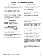
Page 22: ...damaged slats immediately 2 The apron chain tension should be checked and adjusted on occasion If apron chain has slack tightening is required To tighten apron chain loosen the four bolts on bearing a...

Page 23: ...e gun Detail A One Rear PTO Driveline 2 crosses w zerks zerk in inner sleeve Every 25 hours of operation 2 3 pumps w grease gun Detail B Two Top Beater Flange Bearings Every 10 hours of operation 2 3...

Page 24: ...4 4 Section 4 Troubleshooting Maintenance Nitro 275RS Grease Points...

Page 25: ...Nitro 275RS Section 4 Troubleshooting Maintenance 4 5...

Page 26: ...Intentionally Left Blank...

Page 27: ...Nitro 275RS Section 5 Parts Breakdowns Lists 5 1 Section 5 Parts Breakdowns Lists...

Page 28: ...5 2 Section 5 Parts Breakdowns Lists Nitro 275RS Hitch...

Page 29: ...Zinc Hex Cap Screw 6 4 HB 5 8 11X1 75 Z5 Hex Bolt 5 8 11x1 3 4 Grade 5 Zinc Plated Hex Cap Screw 7 6 HB 5 8 18 X2 YZ8 Hex Bolt 5 8 18x2 Grade 8 Zinc Hex Cap Screw 8 2 LN 1 F Center Locknuts 1 12 2 Way...

Page 30: ...5 4 Section 5 Parts Breakdowns Lists Nitro 275RS Front Shields...

Page 31: ...1 2 13x1 Grade 5 Zinc Plated Hex Cap Screw 12 4 HB 1 2 13X1 25 Z5 Hex Bolt 1 2 13x1 1 4 Grade 5 Zinc Plated Hex Cap Screw 13 1 HB 1 2 13X1 5 Z5 Hex Bolt 1 2 13x1 1 2 Grade 5 Zinc Plated Hex Cap Screw...

Page 32: ...5 6 Section 5 Parts Breakdowns Lists Nitro 275RS Front Apron Drive...

Page 33: ...0 7 0 x 62 5 6 3 600 790 Rubber Hold Down 7 2 BEA UCF209 28 Flange Bearing 8 10 CB 3 8 16 X1 5 Z5 Carriage Bolt 3 8 16 x 1 1 2 Grade 5 Zinc 9 8 CB 5 8 11 X2 5 Z5 Carriage Bolt 5 8 11 x 2 1 2 Grade 5 Z...

Page 34: ...5 8 Section 5 Parts Breakdowns Lists Nitro 275RS Driveline...

Page 35: ...28028 CV80 CLS 2 1 39852 PTO 600 750 T60 086P265011 306028 CLS 2500NM 3 1 42110 Drive Shaft Nitro 275 4 4 BEA UCP208 24 Bolt Pilow Block UCPE208 24 National 2 Heavy Housing 5 8 FW 1 2 Flatwasher 1 2 Z...

Page 36: ...5 10 Section 5 Parts Breakdowns Lists Nitro 275RS Rear Apron Drive...

Page 37: ...ent 9 2 37566 375 Rear Scraper Weldment 10 1 42129 Gear Box Torque Arm 11 1 450 371 Bushing Apron Shaft 12 2 700 431 Polygon 2 875OD x2 383 ID x2 75 LG 13 12 HB 1 2 13X2 Z5 Hex Bolt 1 2 13x2 Grade 5 Z...

Page 38: ...5 12 Section 5 Parts Breakdowns Lists Nitro 275RS Endgate...

Page 39: ...e 5 Zinc 11 8 CB 5 8 11 X1 5 Z5 Carriage Bolt 5 8 11 x 1 1 2 Grade 5 Zinc 12 2 CB 5 8 11 X1 75 Z5 Carriage Bolt 5 8 11 x 1 3 4 Grade 5 Zinc 13 2 FW 1 4 Flatwasher 1 4 Zinc Plated USS 14 4 FW 3 8 Flatw...

Page 40: ...5 14 Section 5 Parts Breakdowns Lists Nitro 275RS Beaters...

Page 41: ...13x1 1 4 Grade 5 Zinc Plated Hex Cap Screw 21 16 HB 1 2 13X1 75 Z5 Hex Bolt 1 2 13x1 3 4 Grade 5 Zinc Plated Hex Cap Screw 22 4 HB 5 8 11X1 5 Z5 Hex Bolt 5 8 11x1 1 2 Grade 5 Zinc Plated Hex Cap Screw...

Page 42: ...5 16 Section 5 Parts Breakdowns Lists Nitro 275RS Floor Side Boards...

Page 43: ...s 75 x 154 62 N275 Left 5 2 42174 Sideboard 75 x 139 75 6 1 42635 Floor Board 75 x 154 62 N275 middle 7 4 42356 Floor Boards 75 x 154 62 Nitro 275 Right 8 12 CB 1 2 13 X4 5 Z5 Carriage Bolt 1 2 13 x 4...

Page 44: ...5 18 Section 5 Parts Breakdowns Lists Nitro 275RS Single Axle...

Page 45: ...Stud for 16000 and 20000 Hub 5 2 HB 5 8 11X6 Z5 Hex Bolt 5 8 11x6 Grade 5 Zinc Plated Hex Cap Screw 6 16 HB 5 8 18 X2 YZ8 Hex Bolt 5 8 18x2 Grade 8 Zinc Hex Cap Screw 7 2 HUB 16000 Spreader Hub 16000...

Page 46: ...5 20 Section 5 Parts Breakdowns Lists Nitro 275RS Tandem Axle w o Scales...

Page 47: ...t Rim 6 1 F58 225 Wheel Stud for 12000 Hub 7 1 F58 CONE NUT Wheel Nut for 12000 Hub 8 2 HB 1 2 13X4 5 Z5 Hex Bolt 1 2 13x4 1 2 Grade 5 Zinc Plated Hex Cap Screw 9 16 HB 5 8 18 X2 YZ8 Hex Bolt 5 8 18x2...

Page 48: ...5 22 Section 5 Parts Breakdowns Lists Nitro 275RS Tandem Axle w Scales...

Page 49: ...ud for 12000 Hub 10 32 F58 CONE NUT Wheel Nut for 12000 Hub 11 8 HB 1 8X5 5 SHCS Hex Bolt 1 8 x 5 1 2 Socket Head Cap Screw 12 2 HB 1 2 13X4 5 Z5 Hex Bolt 1 2 13x4 1 2 Grade 5 Zinc Plated Hex Cap Scre...

Page 50: ...5 24 Section 5 Parts Breakdowns Lists Nitro 275RS Apron Runners...

Page 51: ...ain 4 1 42142 275 Left Apron Chain 5 22 37820 375 450 600 SLATS 6 8 HB 3 8 16X1 Z5 Hex Bolt 3 8 16x1 Grade 5 Zinc Plated Hex Cap Screw 7 22 FW 3 8 Flatwasher 3 8 Zinc Plated USS 8 24 LN 3 8 N LN 3 8 1...

Page 52: ...5 26 Section 5 Parts Breakdowns Lists Nitro 275RS Hydraulic Layout...

Page 53: ...31644 HH22 6AT1 6FJX 6FJX HCL 22 8 1 34001 Gear Box for Spreader Apron RT420 9 2 37344 Nitro 375 Gate Cylinder 2 0 x 48 x 1 5 10 1 37871 HH125 6AT1 6FJX 6FJX HCL 125 11 2 42651 HH235 6AT1 8FJX 6FJX H...

Page 54: ...Intentionally Left Blank...

Page 55: ...t Assembly pg 6 2 6 3 Light Kit Wiring Harness pg 6 4 6 5 Electric Flow Control Includes all items except Item 7 on Hydraulic pages pg 6 6 6 7 Electric pages pg 6 8 6 9 Manual Flow Control Includes It...

Page 56: ...6 2 Section 6 Optional Features Nitro 275RS Light Kit Assembly...

Page 57: ...CB 3 8 16 X0 75 Z5 Carriage Bolt 3 8 16 x 3 4 Grade 5 Zinc 10 8 CB 3 8 16 X1 25 Z5 Carriage Bolt 3 8 16 x 1 1 4 Grade 5 Zinc 11 2 CB 7 16 14 X1 5 Z5 Carriage Bolt 7 16 14 x 1 1 2 Grade 5 Zinc 12 2 HB...

Page 58: ...6 4 Section 6 Optional Features Nitro 275RS Light Kit Wiring Harness...

Page 59: ...ht Kit Wiring Harness ITEM QTY PART NUMBER DESCRIPTION 1 1 TL550 200 117 Female 7 Pin Plug 1 31798 Grommet 3 4 31790 Individual Light Wiring 4 2 31788 Red Tail Light 5 2 31789 Amber Tail Light 6 1 369...

Page 60: ...6 6 Section 6 Optional Features Nitro 275RS Flow Control Hydraulics...

Page 61: ...4 1 HF 5502 8 8 Hydraulic Fitting 5 2 HF 8010 4 Male Quick Coupler 6 1 30857 3 4 Flow Control Valve 7 1 30855 Manual Flow Control 8 1 HF 5604 12 12 12 Hydraulic Tee Fitting 9 2 HF 2404 8 12 Hydraulic...

Page 62: ...6 8 Section 6 Optional Features Nitro 275RS Electric Flow Control Wiring...

Page 63: ...ITEM QTY PART NUMBER DESCRIPTION 1 1 37968 Solenoid 2 1 37974 Flow Control 1 37976 Complete Electric Flow Control 3 1 37969 Flow Controller 4 1 37970 2 Prong Plug 5 1 82 2164 Fuse Holder 6 9 EL23662 W...

Page 64: ...6 10 Section 6 Optional Features Nitro 275RS N750LC GT400 N750LCNT460 Scales...

Page 65: ...Nitro 275RS Section 6 Optional Features 6 11 N750LCNT8000 Scales...

Page 66: ...ain and ensuing spreader damage the apron chain safety valve must be opened manually to reverse the apron chain The apron chain safety valve is located on the variable speed control valve at the front...

Page 67: ...Nitro 275RS Section 7 PTOs 7 1 Section 7 PTOs...

Page 68: ...7 2 Section 7 PTOs Nitro 275RS 39850 PTO 375 450 525 600 750 V80 141P028359 028028 CV80 CLS...

Page 69: ...rd Retaining Collar for Inner Tube 38 1 PTO180 016 790 Safety Chains 39 1 PTO165 000 801 Guard Cone Set 40 1 PTO142 981 078 2821 Complete Guard with Instruction Manual 51 1 PTO190 000 451 Outer Circli...

Page 70: ...7 4 Section 7 PTOs Nitro 275RS 39852 PTO 600 750 T60 086P265011 306028 CLS 2500NM...

Page 71: ...3 PTO190 000 078 Ball 58 1 PTO151 016 546 Hub R12 1 3 8 Z6 59 3 PTO151 014 136 Ratchet 60 3 PTO151 014 137 Leaf Spring 61 1 PTO190 000 199 Retaining Washer 62 1 PTO190 000 020 Grease Nipple M8x1 63 1...

Page 72: ...VII Torque Value Chart Imperial Nitro 275RS Torque Value Chart Imperial...

Page 73: ...Nitro 275RS Torque Value Chart Metric VIII Torque Value Chart Metric...

Page 74: ...rs Daily 4 4 Every 40 hrs Weekly 4 5 Every 400 hrs Annually 4 5 Floor Side Boards 5 16 Flow Control Hydraulics 6 6 Fluids Lubricants 4 2 Front Apron Drive 5 6 Front Shields 5 4 General Safety 1 3 Hitc...

Page 75: ...e 3 1 Section 4 Troubleshooting Maintenance 4 1 Section 5 Parts Breakdowns Lists 5 1 Section 6 Optional Features 6 1 Section 7 PTOs 7 1 Serial Number I Single Axle 5 18 Specifications IV Spreader Prep...

Page 76: ......

Reviews: