Copyright © 2019 TTA All Rights Reserved.
M6E-1 Mist Use Instruction
1
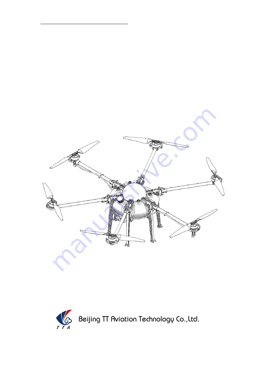
TIANNONG M6E-1 Mist Device
USER INSTRUCTIONS
Make sure the pilot is well-trainned in operating UAVs before going on mission.
Page 1: ...Copyright 2019 TTAAll Rights Reserved M6E 1 Mist Use Instruction 1 TIANNONG M6E 1 Mist Device USER INSTRUCTIONS Make sure the pilot is well trainned in operating UAVs before going on mission ...
Page 2: ...omponent Item Component 1 Fuselage 7 Intelligent Battery 2 Clockwise Arm with LED 8 Landing Gear 3 Counter Clockwise Arm with LED 9 Functional Tank Lid 4 Clockwise Arm 10 Arm Joint Fuselage 5 Counter Clockwise Arm 11 Propeller clockwise 6 Water Tank 12 Propeller Counter clockwise 1 8 12 11 2 3 4 6 7 9 10 5 ...
Page 3: ...ent Battery Installation 15 3 Intelligent Battery Instruction 16 3 1 Key Function 16 3 2 Electricity Inspection 16 3 3 Lifetime Inspection 17 3 4 Charging 17 3 4 1 Charging Protection Function 18 3 5 Reminding Functions 18 3 5 1 Maintenance Reminder 18 3 5 2 Low Voltage Alarm 18 3 5 3 Storage Reminder 18 3 6 Self Balance and Self Storage in Storage 19 4 Charger Station Introduction 19 4 1 Producti...
Page 4: ... Drone Point 33 5 3 4 Route Making 34 5 3 5 Executing Mission 35 6 Remote Controller 37 6 1 Function Description 38 6 2 Bind 38 6 3 RC connection Device Helper APP Introduction 38 6 4 Video Transmitter Introduction 39 6 5 Hand Mode Settings Introduction 40 6 6 Remote Controller Antenna 41 6 7 Flight Control 42 7 Function Control 43 7 1 Flight Mode 43 7 2 AB Mode 44 8 Mist Module 46 8 1 Introductio...
Page 5: ...romagnetic interference environments When using this product please keep away from army and kinds of manned craft flight area Don t use this product in rain thunder sandstorm fog snow high wind and low temperature and other bad environments When flying in more than three kilometers Environmental factors can lead to flight performance degradation please care of using it When operating this product ...
Page 6: ...e pesticide residue in fuselage will be harmful to human body When dispensing please pay more attention and use protective tools and do not let body directly touch with the pesticides After pesticide spraying please clear your skin copter and remote control When using pesticide there will be interaction between different pesticides user should clear cartridge or keep a certain interval time Sprayi...
Page 7: ... buildings high voltage wires and others Please fly the drone in a dedicated space Please ensure the drone fly within the operator s eyesight The drone working temperature is between 0 40 Ensure the drone fly within the permit of local law and regulations To fly the drone safely as required please fly it within in the height of 50 meters If it has local flying height limit within 5ometers please m...
Page 8: ...Ensure flying sites outside of the restricted areas and is proper for flight Please make sure do not fly or operate the drone when you are drunk or with medicine limitation Be familiar with the remote control operation each flight mode and ensure you know how to operate the control condition User shall know and obey all the law and regulations in flying location 1 6 Compass Calibration Requirement...
Page 9: ...fuselage material The big power brushless motor guarantees the sensitiveness and flexibility The Lipo batteries guarantee the power supply and easy to repair and maintain Various spraying tests proves the best performances of this UAV 2 1 TIANNONG M6E 1 Parameter Weight without battery 9KG Max Pitch Angle 35 Standard Takeoff Weight 23KG Best Spraying Speed 4 6m s Max Takeoff Weight 24KG Max Spayin...
Page 10: ... 12S 44 50 4v Working Pulse Width 1000 2000us Compatible Signal Frequency 50 400Hz Drive PWM frequency 400Hz Foldable Propellers Material High strength engineering plastic Diameter Screw pitch 2388 L 585mm Weight 95g Battery Capacity 14000MAh Battery TTA Intelligent Battery 12S Max Climbing Speed 5m s Max Power 12000W Max Landing speed 3m s Hovering Power 3100W Max Flying Speed 15m s Hovering Time...
Page 11: ...g Droplet Diameter 80 200μm adjustable Remote Controller Remote Controller Model No R4 Working Frequency 2 4Ghz Charging time 10h Effective Signal Distance 1 2KM Battery capacity 3 7V 4000mAh Charging type DC 5V 2A Charging time 5 10h Working Environment Temperature 0 40C Best Storage Temperature 10 25C Best Charging temperature 10 25C 2 3 Preparation Before Takeoff 2 3 1 Installation of Fuselage ...
Page 12: ...stall the fuselage and the water tank kit according to the mark 1 3 2 4 It will be completed like Figure3 3 Marking on the corresponding position of the 6 landing gears as Figure 4 4 Slip the landing gear gently into the fillister mark 7 of fuselage as the Mounting Direction arrow of Figure5 Make the bulge mark 5 stuck into the fillister mark 8 and the part mark 6 get into the fillister mark 9 as ...
Page 13: ...ction 9 2 3 2 Arm Installation Make all the arms ready 1 clockwise CW arm with LED 1 counter clockwise CCW arm with LED 2 CW arms and 2 CCW arms Totally 6 arms Motor rotation direction same as the cover Label M1 to same label of copter M1 CCW arm assembly ...
Page 14: ... Rights Reserved Product Introduction 10 Label M2 same as copter frame Motor rotation direction as the cover M2 CW arm assembly Label M3 same as the copter frame rotation direction same as motor M3 CCW arm assembly with LED ...
Page 15: ...ts Reserved Product Introduction 11 Arm label same as the copter s M4 Same as the motor rotation direction CW M4 CW arm assembly Same as the label of copters label M5 Same as the motor rotation direction CCW M5 CCW arm assembly ...
Page 16: ... as the motor rotation direction CW M6 CW arm assembly with LED Copter s M6 same as the copter s M6 Head direction as the arrow Arm M1 same as the copter s M1 Arm M2 same as the copter s M2 Copter s M3 same as the copter s M3 Copter s M4 same as the copter s M4 Copter s M5 same as the copter s M5 ...
Page 17: ... inner hole see figure 9 Female and male matched Figure 8 figure 9 4 Install the M5 49 plug screw from the hexagon side of the 6mm hole on fuselage arm joint see figure 10 5 Lock the plug screw with a M5 nut from the other side the bolt end should same as the the nut that means lock works as Figure 11 Bolt on hex hole Nut in hole M5 shutter screw M5 nut Self lock when bolt end and nut in same plan...
Page 18: ...t have 3 There is a indicate arrow on the Dome which show the nose 4 According to the Figure 7 install CCW arm on M1 and M5 install CW arms on M2 and M4 install CCW Arm with LED on M3 install CW Arm with LED on M6 5 Arm could only fold down instead of up during the installation arm should be in an horizontal level with ESC 2 3 3 Spraying Tube Installation 1 First insert the Φ8 spraying tube into t...
Page 19: ... 4 Intelligent Battery Installation 1 Push the Intelligent battery into the water tank as Figure 15 1 due to interference fit it will be installed well when the battery wear pad stuck into the position Mark 3 in the Figure 15 2 It will be completed like Figure 15 3 2 The whole copter will be completely installed like Figure 15 4 ...
Page 20: ...ge the charge port will be opened when the battery power on and be closed when the battery power off 3 2 Electricity Inspection When the battery is power off you can check the real time electricity with a short press ON flash OFF Power LED1 LED2 LED3 LED4 red orange white Attention Electricity indicate light represents both the quantity of electricity when charge and discharge and also the life of...
Page 21: ...ON Flash OFF OFF OFF Flash 3 4 Charging 1 Setting connecting intelligent battery and charger Step1 Turn on the battery by a short press and a long press according to the instruction Step2 Connect balance connector and then XT 60 then XT90S or AS150 anti spark connector Step3 Start regular charging automatically 2 Electric indicator will flash in cycle and displays the current electric quantity 3 I...
Page 22: ...f there is abnormal short circuit of charging end during charging status charging will be interrupted automatically in order to ensure to not damage to battery cell 3 It will benefit to battery lifetime to set highest protection voltage of each cell according to different charging current Attention Restart should be done after any protection to ensure the abnormal has been eliminated and protectio...
Page 23: ... Balance and Self Storage in Storage 1 Intelligent balance inside battery balance will adjust little to prolong charging and discharging time 2 Intelligent storage battery will adjust to the most suitable storage capacity automatically for long term storage 4 Charger Station Introduction 4 1 Production Parameters 1 Input voltage 190V 220V AC 2 Max charging current CH1 20 0A CH2 20 0A 3 Max chargin...
Page 24: ... Indicator Status LED0 LED1 LED2 Instruction Flash Battery communication abnormal Constant Please check battery connection line or battery voltage status Flash Charging electric circuit abnormal Constant Please contact after sales of factory Charging start stop Fast slow charging storage Charging start stop Balance port Charging port Power switch Charging cable port Main power plug ...
Page 25: ...R input power has been open battery figure L0 on the screen is lightened inner fan begin to rotate and charging channel close at the same time 3 How to charge Turn on the battery by a short press and a long press according to the instruction 3 1 first then connect XT 60 input connector and balance connector separately progress bar of battery type signal flash electric quantity indicator displays r...
Page 26: ...g stop operation for any abnormal phenomenon 4 Be sure charger is far away dust moisture rain heat source direct sunlight vibration and some other unsuitable environment 5 Battery and charger must be placed on uninflammable insulated surface 6 Please follow the strict instructions 5 App Setting of Copter 5 1 Software Configuration 1 Please install the GCS software 2 After GCS installation the labe...
Page 27: ...r authorized changing Remote controller could not unlock before parameters adjustment Exit could only be done when all of the parameters adjustment should be done and confirmed Copter could only fly by restarting after parameters adjustment Parameters could be adjusted when copter connected the steps are as followings 1 Open the OTG function from cellphone SETTINGS SYSTEM OTG the default is Off th...
Page 28: ...ng District Beijing China www ttaviation com 24 2 Bluetooth connection Open the bluetooth function in cellphone Open the bluetooth function in cellphone Set the connect type of APP on Bluetooth mode Connect the bluetooth of remote controller Remote controller Bluetooth name T12_ password 1234 ...
Page 29: ...3 After connection app will be as followings see figure 5 4 5 4 4 Click label at up right corner to enter into parameters adjustment 5 2 1 Remote Controller Calibration Remote controller calibration click the button READ to get the data see the following figure 1 Start to calibrate connect copter with GCS click RC CHANNEL move the stick to ...
Page 30: ... button ACCELEROMETER LED will flash in red green yellow alternately LED green means successful calibration data will be stored by restart 5 2 3 Compass Calibration Calibration order Two kinds of method of compass calibration 1 Click the button COMPASS to enter into calibration status 2 Switch switch E back and forth more than 4 times to enter into calibration status Calibration Step 1 Confirm GCS...
Page 31: ...ly and LED will flash normally if successful LED will keep red for 3 seconds If fails user need to calibrate again 4 Please power again after successful calibration Attention 1 Compass should be done after changing flying area 2 Calibration should be done in outdoor wild and far away from high tension line tower which is easy influenced by magnetic interference 3 Keep horizontal and vertical durin...
Page 32: ...n Settings Five voltage protection options for user to select Close close the protection return auto home landing Hang hovering Land auto landing Hang Land hovering and then landing User could choose the one suitable The default is Return Home landing 5 2 5 2 Alarm Voltage Settings Settings of first alarm and second alarm It s recommended to 43 6V for the first alarm and 43 1V for second alarm LED...
Page 33: ... before delivery 5 2 5 4 Low Liquid Protection When liquid is nearly out the following reaction could be set Off Close the protection Return auto home landing Hovering Hovering landing The default is Off which means only LED flash as alarm We suggest you to set it on Return option 5 2 5 5 Spraying Mode The drone has 2 spraying modes Combination Manual mode Combination mode Spraying rate will follo...
Page 34: ...ail Safe status and execute the set Fail Safe action The default set is Automatic return which means Return To Home automatically Besides Lost Comms Continue Path is used to set whether drone will continue the mission after lost control during a mission flight If it is open drone won t execute Fail Safe action until its mission has been completed The default setting is Close 5 2 7 Map Coordinates ...
Page 35: ... position deviation is obvious 5 3 Route Establish Four Automatic Operation modes Map Point Dot Equipment Drone Point Phone Dot Map Point mode Dot on a built in map to plan route Dot Equipment Use a Dot Equipment to make boundary points Drone Point Drive drone to mark boundary points Phone Dot Use Phone to mark boundary points 5 3 1 Start Route Establish 1 Click to enter into route interface 2 Cli...
Page 36: ...Building Niantou Industrial Park Changping District Beijing China www ttaviation com 32 5 3 2 Map point 1 Select Map Point 2 Click adding area and click the boundary point on map to set the working area Obstacles could be added by clicking add obstacles ...
Page 37: ...ng District Beijing China www ttaviation com 33 5 3 3 Drone Point 1 Select Drone Point 2 Click adding area to set working area Obstacles could be added by clicking add obstacles 3 Fly drone to the first boundary point Click Common to make the first boundary point Then the second third fourth ...
Page 38: ... 5 3 4 Route Making Click Create to confirm the chosen area and enter into Adjust Route interface Swath Distance between 2 spraying routes Obstacle gap Distance around the obstacle Target gap Distance between working area and boundary Offset Translation of working area Save Save the task After editing completed click Save to save the task ...
Page 39: ...ina www ttaviation com 35 5 3 5 Executing Mission 1 Click Task to enter into Task Management interface Click Send Mission to upload the task Two Mission Task Modes Block and Edge Block mode Drone will only fly along the route Edge mode Drone will automatically fly along the boundary line after finishing the route ...
Page 40: ...Industrial Park Changping District Beijing China www ttaviation com 36 2 Click to take off from GCS or remote controller click start task to execute the route Rudder and Throttle could be operated during flying obstacles could also be avoided by moving the Aileron stick ...
Page 41: ...aged smoking or abnormal heating charger should not be used Charging should not be continued in condition of smoking smelly weeping Charging should not be in the area of baby playing Charging should not at temperature more than 60 G E H F A Y2 Y1 X1 X2 D 3 Segment Lever 3 Segment Lever Waterproof Dustproof Stick Power button Output 5V Battery lamp Charging Date transmitting interface Button 2 4G 3...
Page 42: ... Drone will bind the remote controller successfully with a voice prompt Remote controller need to be calibrated after binding Remark Binding remote controller can not be operated for more than one pair at the same time Only one to one pairing is allowed 6 3 RC connection Device Helper APP Introduction 1 Turn on remoter controller short press long press Open bluetooth search and connect bluetooth o...
Page 43: ... 39 6 4 Video Transmitter Introduction 1 Download and install FPV APK into user s phone FPV APK link https www ttaviation org wp content uploads 2019 06 M4EM6E 1M6E XM8 A Pro 2 45 APK_ zip 2 Open OTG function of cellphone to give permission of data transmission Connect the phone and remoter controller with USB cable Power on the drone ...
Page 44: ...hangping District Beijing China www ttaviation com 40 3 Video will be displayed on the phone after user click the OK option 6 5 Hand Mode Settings Introduction 1 Connect user s phone remote controller and drone 2 Open Device Helper APP click HAND SETTINGS and select hand mode USA or JPN ...
Page 45: ...ng Niantou Industrial Park Changping District Beijing China www ttaviation com 41 6 6 Remote Controller Antenna Remote controller antenna should straight up when it is stretched Caution Incorrect directions as the two pictures below Straight up when stretched ...
Page 46: ...the 10 position from neutral in 3 seconds 5 After landing the aircraft push the throttle down and hold for 3 seconds The motors will be stopped Cautions 1 It is suggested to take off in GPS mode if satellites is more than 14 no magnetic field interference and all parts of aircraft are in good condition 2 Before take off please check the stick mode and confirm the current settings is the mode you w...
Page 47: ...itter operation empty tank reaction others GPS satellites enough LED does not flash red AB mode Copter will fly and spray along with AB point Record point A and B and switch to AB mode choose left or right for roll GPS satellites enough LED does not flash red Return mode Copter will fly back home point automatically flying back tail to home point and then descend slowly it could be controlled afte...
Page 48: ...e controller have voice prompt 2 Record the point B drive the drone to the position you want be sure it is at least 10 meters away from point A Until the drone self hovering steadily switch F to Point B memorized After that the LED flash yellow for 2 seconds The controller have voice prompt 3 Select the direction switch E Flight mode to AB mode move the roll joystick to select the roll direction M...
Page 49: ...pesticide action to self hovering or return in AB mode this function still works When set the low battery action to return in AB mode the this function still works After the spraying work is done AB mode can be shut down by switching into altitude mode 6 To return to the breakpoint after broke the AB mode route automatically or manually Filling the pesticide in the tank and taking off then switch ...
Page 50: ...t is as high as 97 It indicates the best performances of this module Safety Instruction Since the fog machine works in high concentration smoke pesticides it is easy to bring corrosive damage to the product Therefore after working every day please clean the fog machine to keep the fog machine dry and no drug residue on the surface Because the outlet hole of smoke machine will have some pesticide p...
Page 51: ...dy directly touch with the pesticides After pesticide spraying please clear your skin copter and remote control When using pesticide there will be interaction between different pesticides user should clear cartridge or keep a certain interval time Spraying shall be carried out in windless sunny day don t spray under high temperature at noon While breezing the operator should be standing above the ...
Page 52: ... Gas Composition 30 Propane 70 Isobutane Gas Endurance 40min 50min bottle 230g 8 4 Concise Use Process Check the connection of all fasteners and connectors to avoid any loose possibilities Check the propellers to avoid any inversions Check battery capacity of RC settings of all channels and sticks function Turn on RC power on drone and check all flight parameters to ensure all parts work well Chec...
Page 53: ...jing TT Aviation Technology Co Ltd Add No 1 TTA Building Niantou Industrial Park Changping District Beijing China www ttaviation com 49 8 5 Remote Controller of mist device Ignite button Pump switch button ...
Page 54: ...Co Ltd Add No 1 TTA Building Niantou Industrial Park Changping District Beijing China www ttaviation com 50 8 6 Assembly Diagram A B C D E F A Butane inlet D Heat sink B Fan E Butane bottle C Circuit control box F Main heating sector ...
Page 55: ...al Park Changping District Beijing China www ttaviation com 51 8 7 Using Instruction 1 Tighten the Gas tank to the valve A counterclockwise make sure there is no loose between the tank and valve 2 Inject the drug liquid into the drug cabinet and press button B to let the liquid ...
Page 56: ...ate the valve B counterclockwise for more 5 quickly Press Button A once again and wait for approximate 2 seconds Some current sound of spark plug will be heard then the gas in the mist device will be ignited and burn stably 6 5 seconds after the gas burning stably press button B to open the pump to let the drug liquid enter into the mist device 7 The fog will increase with the rising of temperatur...
Page 57: ... smoothly 3 Blades should be folded well and be held by the blade holder or belts after flight and should be released and put straight before take off 2 Motors 1 Motors should be or be suggested to be replaced 2 Before the rotor clearance get loose or running after 3000 hours 3 The rotor movement get blocked 3 ESC should be or be suggested to be replaced 1 When Esc output obviously different from ...
Page 58: ...k flash High Compass Calibration Horizontal calibration Yellow light constant light Middle Vertical calibration Green light constant light Middle Calibration failed Red light constant light Middle Calibration succeed Red green and yellow light alternating flash Middle Accelerator Calibration Calibrating Red green and yellow light alternating flash Middle Calibration succeed Green light constant li...
Page 59: ...ditions of all safety instructions It s user s commitment to their own behavior and therefore is responsible for all the consequences Users promised to use this product only for legitimate purposes and agree to these terms and any others policies or guidelines TTA company may develop 5 In the process of using this product please be sure to strictly obey the safety instructions included in this doc...