Preventing reverse rotation of inclined or vertical conveyor systems is one of the most common applications for BACKSTOPS.
There are many configurations of conveyors systems that employ BACKSTOPS.
This paper presents the most common types and provides examples and calculations needed to properly size BACKSTOP in
order to maximize performance and improve safety of the conveying system.
*Suggested arrangement may not meet local design standards, please check local design standards.
BACKSTOP Mounting Arrangements
Mounting arrangement
Figure 1
Figure 2
Figure 3
Single and Dual Drives
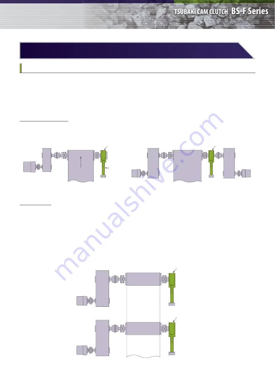
BACKSTOPS for low speed overrunning type are installed directly on the extended head shaft, as shown in Figure 1 and 2.
TSUBAKI recommends the single installation of the BACKSTOP to prevent the reverse rotation of head shaft.
Tandem Drives
When the conveyor arrangement calls for a primary and secondary drive, as shown in Figure 3, the BACKSTOP on the
primary drive unit holds the full load. The BACKSTOP on the secondary drive unit holds the back tension from the belt.
It keeps belt traction on both conveyor systems.
TSUBAKI recommends that the BACKSTOP, having the torque capacity equal to the sum of the primary and secondary
motors, be installed on the primary drive unit.
The BACKSTOP for secondary drive should be sized from secondary drive motor only.
*Suggested arrangement may not meet local design standards, please check local design standards.
Motor
Speed
Reducer
Belt Conveyor
BACKSTOP BS-F
Torque
Arm
Motor
Speed
Reducer
Belt Conveyor
BACKSTOP BS-F
Motor
Speed
Reducer
Motor
Speed Reducer
Belt Conveyor
BACKSTOP BS-F
P R I M A R Y
Motor
Speed Reducer
BACKSTOP BS-F
S E C O N D A R Y
4


